> If you can supply the answers to those questions
Thanks, but ChrioN can only post one maybe two facts at a time, and I won't play 20 Questions.
On the facts so far:
> 32-300 ohms cans
24V supply on two 32-ohm loads can be 0.75 Amps peak, and full-power sine could be nearly a quarter-Amp average. That's ASS-uming a simple AB output stage... if class A, the sky is the limit (actually your heatsink budget is the limit).
Yes, such levels in headphones would probably blow your brains out through your nose. Whether this is desirable or not is a fact I do not have.
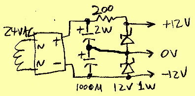
If the fact is that users might come anywhere close to brain-blowing levels in lo-Z phones, then you will want 1,000u caps across the Zeners. The proposed plan will deliver "50mA", but NO more (maybe 55mA), not even for an instant. Which is a safety feature for builders who may not know their true demand; it is more likely to punk-out than to smoke stuff. And while the caps won't support a full power sine test, on speech/music signal they will probably support all you could expect from +/-12V supply.
> has a gain of 8, so it can go reasonably loud.
Does not follow. Gain is not loudness until you know source. If the source is a 10mV low-line-level, it won't be real loud. If the source is a +18dBm bus, gain less than unity will be "loud" in 32 ohms.
My own HP amp has maximum gain of 50, smoothly controllable to less than unity, so that I can tap anywhere in an audio system and bring it to desired level. This includes bringing "silence" (room rumble and mike hiss) up to medium-loud so I can judge noise quality. Not normal listening.
FWIW, both my HP amps start from a single 24VAC winding. But I did not then arbitrarily throw a "+/-12V" spec on it.
The older one rectifies 24VAC to 36VDC, drops 3V in an R-C filter, and dumps that on BIG resistors to the collectors of a couple TIP120 transistors and the + pin of a TL072 op-amp. This is ample filtering for that topology. The box hums faintly because the PT is 2 inches from the input jacks.
This one runs capacitor-output. The collectors sit 12V above common and that must be blocked. A 470u 16V cap is not expensive. Some may say that cap-coupling is bad... well, there is NO way to mix DC and AC for a wall-powered amplifier without either a cap or a choke in the path somewhere. In "capacitorless" designs it typically lurks in the power supply, and its flaws may be reduced by NFB. Although in many real cases, capacitor currents dumping into signal traces do more harm than a simple cap-coupled output. And when "capacitorless" outputs blow short, they usually take a speaker with them... cap-coupled usually doesn't.
The other one starts with a saggy 24VAC wall-wart, doubles that to +/-31VDC. This raw voltage is applied to the several power transistor collectors. It also runs through 3906-like transistors with 2*9V Zeners to give +/-17.4V (actually +17.2V/-17.6V; a little unbalance should never hurt) to run opamps, then diode-droppers to give +/-16.8V on the second stage (a work-around for the phase catastrophe of overdriven Bi-FET opamps).
I don't feel like regulating Main Power when it is not needed. If you hold the base of a PN3055 or TIP120 firmly, inside overall NFB, fairly raw power does not ripple the output; indeed this connection has roughly the same ripple rejection as a regulator. The heatsink I wudda needed on a regulator can be added to the power transistor, saving pennies, parts, and work. Then the little stuff which could not stand 62V supply can be regulated with a 13-cent plastic transistor.
The second amp has considerably more output voltage than something run on "+/-12V", yet will not cause nose-bleed on some 300 ohm phones. It is not uncommon for serious users to want +/-18V even +/-24V to completely eliminate transient clips on some 300r cans. So I'm thinking, if you have 24VAC=35VDC, you may want to use it all. There are plenty of 36V chips. However lacking a center-tap or some other elegant way to get a mid-point, you will need a mid-reference and a capacitor-coupled output. Non-elegant ways include an "passive rail splitter" which leads to DC offset and low bass separation, or "active ground channel" which demands an amp twice as big as either channel and adds unnecessary cross-channel intermodulation.
