Marshall Major (200W) Amp - anyone familiar with it?

GroupDIY Audio Forum

Help Support GroupDIY Audio Forum:

This site may earn a commission from merchant affiliate links, including eBay, Amazon, and others.

Michael Tibes

Well-known member
Joined
Jun 5, 2004
Messages
889
Location
Berlin, Germany
I have a Marshall Major Top which needs some attention. I've done some research on the net, but all I was able to figure out yet is that these amps are kinda difficult because the design itself is beyond some specs (B+ @ 650V while the originally used KT88 tubes are speced for 450V http://dawkmods.proboards.com/index.cgi?board=AskDawk&action=display&thread=336) and this very high voltage leads to 'high voltage problems' which typically don't occur on 50/100W amps. There is a lot of talk, the usual guesswork of selfdeclared 'experts' and probably a few real experts which only want to state that they know but don't want to tell...

So my amp seems unmodified at first glance. It does blow a 4AT mains fuse occasionally (no matter whether it's being played or not), the labeling on the amp says this fuse should be 3A, the schematic and some folks on the net say it should be 5A?? If 5AT was right, then it's probably no surprise 4A blows, even when it's not played?
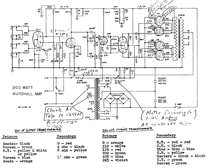
200w.gif


Does someone know what really should be done to these amps in order to improve reliability? The sound of the amp is already awesome as it is, it would be a real loss if it would blow up.

If someone knew what the 'Blackmore mods' were, it would be terrific... Just dreaming, this seems to be a well hidden secret.

This guy here http://dawkmods.proboards.com/index.cgi should really know about the amps, but the interesting sections in his forum are closed and he keeps writing his book where 'everything is going to be revealed'. I'd love to buy it - if it was finished...

Does anyone have experience with these manuals / DVDs http://www.leejackson.com/MasterSeries/index.html? Is it useful information?

Thanx,

Michael
 
Your schematic shows a 5A fuse, and neutral wired to the 110V tap. So this is for the 'export' version.

Since your location is Berlin, I assume that yours is wired for 220V operation, thus the 3A labeled on the amp.

Dunno what your AC wall voltage is, but since nowadays 230V is more 'standard' than 220, it could be a good idea to rewire your primary to the 245/250 tap of the PT.

The main problem with those amps is to find power tubes that can withstand 650V plate voltage...

Axel
 
There's an interesting article covering some practical issues & historical info in Butterylicious' post here:

http://www.groupdiy.com/index.php?topic=39718.0
 
The KT88s originally used had a design maximum of 800V anode voltage. The problem is the screen grid (g2) voltage spec is only 600V. This output stage is ultra-linear, meaning g2 is connected to a tap on the output transformer (which provides some negative feedback), so g2 will be close to full HT voltage with no signal present. They just about got away with it. Current production KT88s aren't as good as the original GEC/MOV ones, but should still be usable (although they won't last as long).

When does the fuse blow? When turning on the power, when turning on the standby switch, or when it's switched on and idling? Is the bias current set correctly? If it blows when turning on the main power switch it could be faulty smoothing capacitors. If it blows when turning on the standby switch it could be the power valves (usually if power valves are shorting the HT fuse blows before the mains fuse, but not always).

Although 230V is the official European standard mains voltage, here in the UK it's still 240V. In many other EU countries it's still 220V. Check your ac voltage with a meter.

To improve reliability (and safety), adding bleeder resistors across the smoothing caps to equalise the voltage across them would be a good idea (essential IMO). If the smoothing caps are original they'll probably need replacing too. If the power valves need replacing NOS KT88s would be best, but these days you need to be rich to afford them. If it has original GEC/MOV KT88s keep them unless they really do need replacing.

The Blackmore mods IIRC were just to rewire the preamp in a master volume configuration similar to the 2203 and 2204 models (possibly with the addition of another valve stage to retain both sets of inputs).

Last but not least, bear in mind that the HT voltage in these amps is LETHAL. When I was a test engineer at Marshall in the '80s, only the most senior test engineers were allowed to work on these because they were so dangerous. No disrespect intended, but unless you have sufficient experience of working with these voltages to do it safely it would be wise to leave it to a qualified amplifier tech.
 
A link between the 2 series 100uF||56k for voltage balancing seems missing as well.
Does the paralleling of the bridge rectifiers really work to increase current rating? I always thought, there will always at least be one diode inside with a slightly different parameter dying first and blowing the remaining paralleled one at the following AC cycle.
 
Harpo said:
Does the paralleling of the bridge rectifiers really work to increase current rating? I always thought, there will always at least be one diode inside with a slightly different parameter dying first and blowing the remaining paralleled one at the following AC cycle.
It will increase current capacity, but won't quite double it. As you say, one will always fail first. Low value resistors in series with each rectifier would make them share current more equally, but these days there are probably bigger and better rectifiers available if you're not too worried about originality.
 
Thanx for the input :)

The fuse blows without obvious reasons, the last time it happened was during a pause with no signal present (not in standby). I am aware of the dangers due to the high voltage, I have been modding my amps for probably 25 years now, but that beast certainly derserves some special respect.

I gotta check if it has the dual rectifiers, it does seem to make sense replacing that with a modern type. I prefer reliability over originality.

And yes, my mains voltage here in Berlin is 230V.

I will browse Dawks site and collect the available bits from there, it is quite spread over various articles. Adding clamping diodes at the output transformer does anyway make sense, doesn't it? I remember I used to use 3 x 1N4007 for these (gotta recheck my groove tubes book), but there might probably be better (faster?) types nowadays?

So far I found these other mods recommended by Dawk:
-replacing the feedback resistor with a 100k one
-changing the bias caps for 47uF/150V types
-making the screen resistors 1k / 25W types
-realigning the output transformer leads from inside the chassis to the outside in order to prevent internal feedback

I guess that the extra preamp tube he put into Ritchie's Majors might have gone to V2 at the 470k mixing resistors because it was mentioned that the amp was still usable with the stock inputs. That seems to be the logical point, doesn't it? It would be great to know this mod in detail, especially since the amp could still be used in the original mode.

I found several comments that using a major with a distortion pedal might blow up the amp, could that be due to the ultralinear OT concept in combination with the close to the limit high voltage? The issue seems absurd to me at first, especially since Ritchie's tone wasn't exactly clean, but maybe there's some truth in it? Dawk on that:
WHEN A BOOSTER OR SOME KIND OF OTHER PEDAL WAS USED TO MAKE SOME DISTORTION THE (650) VOLTS OF B+ WOULD JUMP TO (1800) VOLTS THAT'S CALLED ''PRV'' VOLTAGE...

THE OPTX IS WORKING SORT OF LIKE A ''FLY-BACK'' TRANSFORMER IN A TV SET,,, THAT WHAT'S PRODUCING THAT HIGH ''PRV'' VOLTAGE...

THEN THE (B+) @ (1800) VOLTS WOULD ''ARC'' OVER TO THE CLOSEST GROUND,,, USUALLY BETWEEN PINS (2) AND (3) ON THE OUTPUT TUBES CAUSING A LOT OF SMOKE,,, BURNING OF THE TUBE SOCKET AND A REAL BAD SMELL... ''THUS LEAVING A ''BIG'' BLACK CARBON MARK INSIDE THE CHASSIS WHERE IT ARCED''...

''THIS WOULD HAPPEN SO FAST THAT IT DIDN'T HAVE TIME TO BLOW THE FUSE...

I don't fully understand how the B+ voltage can 'jump' to 1800V, is it due to the waveform produced by a distortion panel or due to the spike which might occur when the panel is switched on? And I thought the clamping diodes should take care of the problem??

Is there any good tip for an improved impedance selctor? The original one looks rather worn. I found these 2 and the one from Banzai probably seems more rugged?
http://www.banzaimusic.com/Rotary-Switch-1x3-BBM.html,
http://www.wolfton-audio.de/shop/article_1479/Marshall-Impedanz-Schalter-_-Impedance-Select.html?shop_param=cid%3D16%26aid%3D1479%26

Rechecking the schematic I realize that the main HT smoothing caps don't have balancing resistors, adding those should make sense? What would be a resonable value - something like 56k or 100k (gotta calculate the wattage)?

Cheers,

Michael
 
If your amp is wired on the 220V tap, then 230V mains voltage should give you around 680V B+, which doesn't help...

The KT120, as cited in the link that Lassoharp posted, seems to be the best choice nowadays for this type of amp (reliability over originality)

The 6A current rating of the Banzai switch is not enough for 4Ω operation.

I'm not sure why the HT smoothing caps would need balancing resistors since their common node is already wired to the center tap of the secondary, thus referenced to half B+.

Axel

 
mad.ax said:
I'm not sure why the HT smoothing caps would need balancing resistors since their common node is already wired to the center tap of the secondary, thus referenced to half B+.
You're right, I missed that.  I still like bleeder resistors to be there to discharge the caps when it's turned off (been bitten too many times by charged smoothing caps).
 
Michael Tibes said:
I don't fully understand how the B+ voltage can 'jump' to 1800V, is it due to the waveform produced by a distortion panel or due to the spike which might occur when the panel is switched on? And I thought the clamping diodes should take care of the problem??
I'd expect clamping diodes to take care of that. I tend to add those to all valve amps I service these days unless I'm asked not to. Lately I've been using a single 2kV diode per side on most of them, although I might put two in series when HT voltage is this high. A few 1kV diodes in series will also work. I haven't had problems with recovery time using standard diodes on other amps, but using fast recovery diodes like UF5408 (3 in series per side) wouldn't hurt here.
 
Michael Tibes said:
So far I found these other mods recommended by Dawk:
-replacing the feedback resistor with a 100k one
-changing the bias caps for 47uF/150V types
-making the screen resistors 1k / 25W types
-realigning the output transformer leads from inside the chassis to the outside in order to prevent internal feedback

The resistor and cap changes look sensible. It might be possible to re-route the transformer wires inside the chassis or add screening rather than put them outside.

Is there any good tip for an improved impedance selctor? The original one looks rather worn.
You could try a 3 way 4 pole rotary switch with all four poles in parallel. As long as the total current rating is high enough for 4 ohms (I'd suggest 10A minimum) it should be OK.
 
johnR said:
mad.ax said:
I'm not sure why the HT smoothing caps would need balancing resistors since their common node is already wired to the center tap of the secondary, thus referenced to half B+.
You're right, I missed that.  I still like bleeder resistors to be there to discharge the caps when it's turned off (been bitten too many times by charged smoothing caps).

Agreed. The two 56K resistors above V3 should take care of that, but in case of the HT fuse blowing you're left with fully charged caps.

Axel
 
mad.ax said:
johnR said:
mad.ax said:
I'm not sure why the HT smoothing caps would need balancing resistors since their common node is already wired to the center tap of the secondary, thus referenced to half B+.
You're right, I missed that.  I still like bleeder resistors to be there to discharge the caps when it's turned off (been bitten too many times by charged smoothing caps).

Agreed. The two 56K resistors above V3 should take care of that, but in case of the HT fuse blowing you're left with fully charged caps.

Axel

Absolutely right, I'd overlooked the center tap arrangement as well :-[
Adding a bleeder resistor there is a must, what would be a reasonable value? 470k? I've read about someone trying to replace a broken HT fuse many hours after it blew and he got zapped badly from the remaining voltage at the fuseholder  :eek:

Michael
 
470K would draw just under 1 watt, but would take more than 80 seconds to discharge the caps...

You may want to share the load between two resistors (1 per cap). A pair of 47K/5W should do the trick in about 16 seconds.

Axel
 
If youre gonna mod your amp, install bleeder resistors now! Do it!
Its better to be a modder, than to be dead-...
 

Latest posts

Back
Top