Kingston
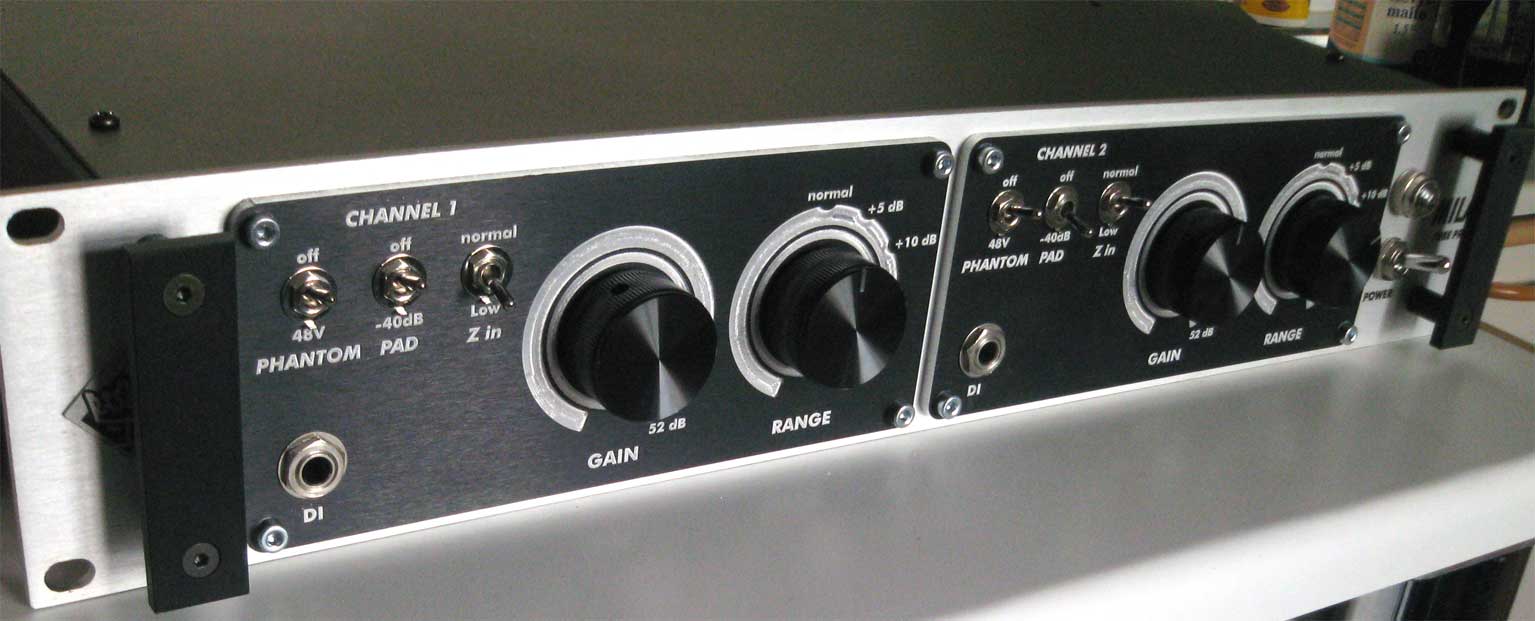
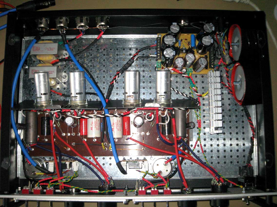
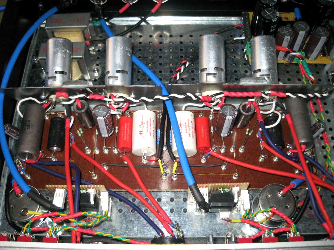
Well-known member
I built quite the MILA-1 preamp here. It should really be called MILA-2 because I've extended the features and ranges significantly. Max gain is about 80dB, way more than the original due to more relaxed output stage feedback range. The layout is an ultimate success. This is my first project where I don't see a trace of 50hz hum even at max gain looking at FFT plots. Careful planning, paranoid shielding of wires and lots and lots of mistakes in past projects finally paid off. Sturdy copper bus ground helps I guess. Power supply is a regulated (250V B+ and 12.6V heaters) brute force thingy, reminiscent of G9 with some (probably unnecessary) tweaks like additional RC networks.
Transformers are Cinemag CMMI-10C input, CM-9589L output.


I didn't test the feedback "range" switch before having the panels engraved and it actually goes to about +30dB, unfortunately not shown on the panel now. I actually didn't quite get why newyorkdave had intentionally limited the feedback range with the mere 3-way switch, and used the unnecessary parallel resistor configuration for the output feedback. 6-way double pole rotary switches are just as cheap, and one can easily extend the feedback range from 50k to no-feedback and anything in between.
And the overdrive is very controllable and good sounding this way. Maybe NYD only likes linear amplification.
One other thing I learned here: always laser fonts and graphics if you can. The graphic "wheels" around knobs show some engraving crud. I told the engraving guy to "cut corners and save time when you can" and that's the result. At least it only shows in pictures with a camera flash. Since this is anodised black panel, laser would have been ideal.
The reason for doing this type of "dual layer" front panel is because I can.


Those veroboard bits near front panel are input modules (pad, phantom and impedance switches). They don't belong on the thick turretboard and I was running out of space anyway. I used relays because I got paranoid about hum, not because I absolutely needed them.
Phantom PSU PCB is another veroboard slap-in module I did not yet wire in.
The layout was originally a bit nicer, but I found out about these awesome russian PIO caps after I had already build this. In they went, fitting just barely. Next project will have only PIO caps in the audio path. I don't care how big they are, they just sound so much better.
This is the best preamp I have ever heard. It's going to be hard for me to top this. It's probably going to have to be something quite exotic, maybe single ended output, and I'm ready to design my own from the ground up this time.
Mike
[edit]
I posted the turret board layout I used on this project somewhere else on the forum long a go. Obviously it should be linked here as well:
http://www.michaelkingston.fi/files/mila-1_turret_layout_kingston.pdf
That file was actually used as a drill template taped on the turret board. If you're going to do that make sure the paper is scaled to correct size for the caps.
[edit]
might as well collect all the documentation here.
The original schematic by NYD: http://groupdiy.com/index.php?action=dlattach;topic=38699.0;attach=23436
Transformers are Cinemag CMMI-10C input, CM-9589L output.


I didn't test the feedback "range" switch before having the panels engraved and it actually goes to about +30dB, unfortunately not shown on the panel now. I actually didn't quite get why newyorkdave had intentionally limited the feedback range with the mere 3-way switch, and used the unnecessary parallel resistor configuration for the output feedback. 6-way double pole rotary switches are just as cheap, and one can easily extend the feedback range from 50k to no-feedback and anything in between.
And the overdrive is very controllable and good sounding this way. Maybe NYD only likes linear amplification.
One other thing I learned here: always laser fonts and graphics if you can. The graphic "wheels" around knobs show some engraving crud. I told the engraving guy to "cut corners and save time when you can" and that's the result. At least it only shows in pictures with a camera flash. Since this is anodised black panel, laser would have been ideal.
The reason for doing this type of "dual layer" front panel is because I can.


Those veroboard bits near front panel are input modules (pad, phantom and impedance switches). They don't belong on the thick turretboard and I was running out of space anyway. I used relays because I got paranoid about hum, not because I absolutely needed them.
Phantom PSU PCB is another veroboard slap-in module I did not yet wire in.
The layout was originally a bit nicer, but I found out about these awesome russian PIO caps after I had already build this. In they went, fitting just barely. Next project will have only PIO caps in the audio path. I don't care how big they are, they just sound so much better.
This is the best preamp I have ever heard. It's going to be hard for me to top this. It's probably going to have to be something quite exotic, maybe single ended output, and I'm ready to design my own from the ground up this time.
Mike
[edit]
I posted the turret board layout I used on this project somewhere else on the forum long a go. Obviously it should be linked here as well:
http://www.michaelkingston.fi/files/mila-1_turret_layout_kingston.pdf
That file was actually used as a drill template taped on the turret board. If you're going to do that make sure the paper is scaled to correct size for the caps.
[edit]
might as well collect all the documentation here.
The original schematic by NYD: http://groupdiy.com/index.php?action=dlattach;topic=38699.0;attach=23436


![Electronics Soldering Iron Kit, [Upgraded] Soldering Iron 110V 90W LCD Digital Portable Soldering Kit 180-480℃(356-896℉), Welding Tool with ON/OFF Switch, Auto-sleep, Thermostatic Design](https://m.media-amazon.com/images/I/41gRDnlyfJS._SL500_.jpg)


