


Bo Deadly
Well-known member
Consider the following circuit:
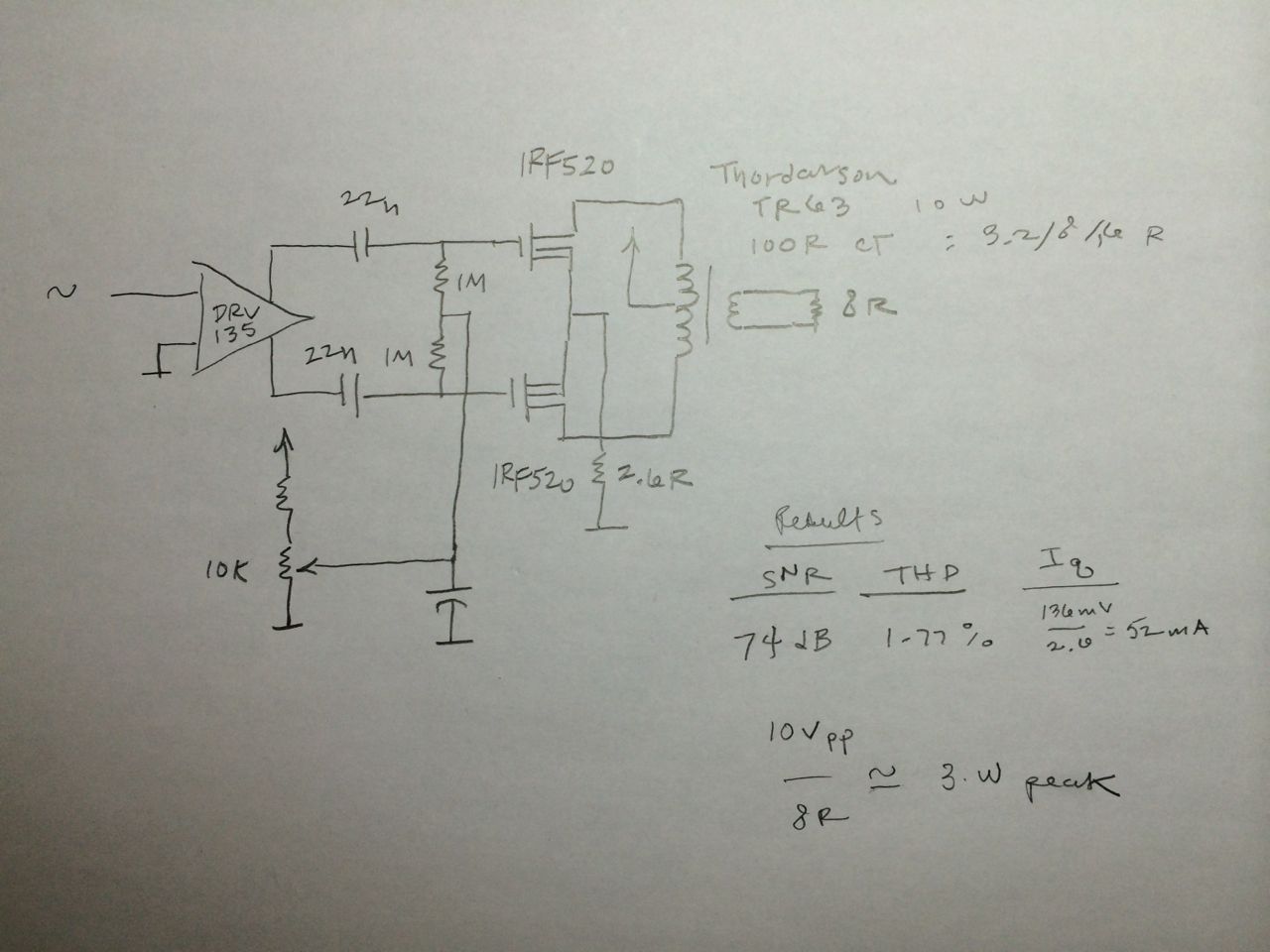
Can someone recommend how I might get a little better linearity out of this?
Ultimately the intent is to explore the "compression" effects of a single supply non-complementary push-pull by playing with the supply impedance. And I also want to explore dynamic bias to produce "explansion". But that's a different discussion. For now I'm just trying to understand what sort of performance I can hope to get from a circuit like this. Specifically, I'm trying to get the maximum linearity with this circuit topology.
Also I am seeking the lowest quiescent current possible vs the maximum power. Meaning ideally it should have very low quiescent current but when there is significant signal the current drawn from the supply is many times greater. So if I could make that ratio 10:1 and get sub-1% linearity, that would be fantastic.
If I look at the waveform visually it seems like as I adjust the bias it goes from horizontal crossover distortion to a triangle wave to vertical crossover distortion. So what is causing the triangle wave effect and how do I minimize it?
UPDATE 1:
For posterity here is the latest circuit and SNR / THD results:
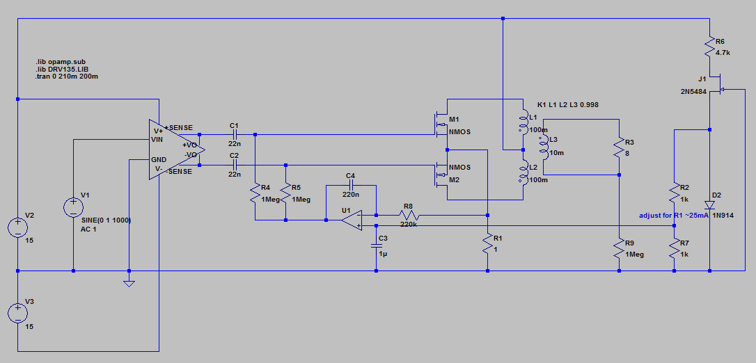
Currently, with the circuit as shown and a ~27.5 mA bias Iq(R1), according to my QA400 analyzer I get:
SNR: 62 dB
THD: 0.28 %
Not bad for a guitar amp. But it might just be the limit of what I can get out of this old transformer. The harmonics responsible look fairly harmless:
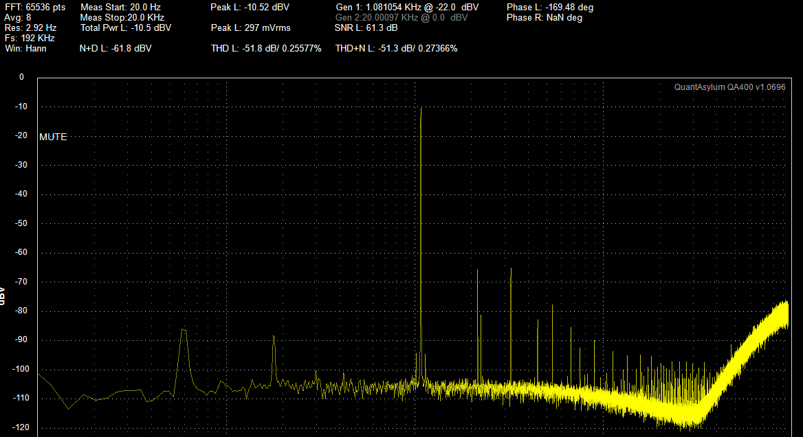
As I raise the input level however the distortion goes up dramatically. I just did the test at a particular level where the THD was minimized (-10dB on the QA400). As the level gets higher, the waveform visually has the horizontal typical crossover distortion.
I also have to correct my comment below about the drain resistor improving performance - it does not. If the output level is adjusted to be a particular level, changing the drain resistor from 2.6 to 1.6 to 1.0 has little effect on THD.
I hope to explore a dynamic bias (adding voltage to servo+ or subtracting current from the servo-) such that the bias is increased if the signal goes above a certain threshold. My thought is that this would reduce said distortion and basically make a sort of expander or noise gate since gain increases with bias. Then I might be able to push the whole thing into clipping without going through the crossover distortion.
UPDATE 2:
The servo bias in the above circuit does not work. There is significant DC shift across the common drain resistor as the signal level is increased such that it causes the bias to shift lower. Even with a relatively slow servo, if the signal is sustained, it will start to bias off the transistors and cause serious crossover distortion. If I use a simple fixed bias the circuit is much more consistent at all signal levels. Of course it should use a proper temperature compensation circuit but I think I've played with this enough for now ...
Can someone recommend how I might get a little better linearity out of this?
Ultimately the intent is to explore the "compression" effects of a single supply non-complementary push-pull by playing with the supply impedance. And I also want to explore dynamic bias to produce "explansion". But that's a different discussion. For now I'm just trying to understand what sort of performance I can hope to get from a circuit like this. Specifically, I'm trying to get the maximum linearity with this circuit topology.
Also I am seeking the lowest quiescent current possible vs the maximum power. Meaning ideally it should have very low quiescent current but when there is significant signal the current drawn from the supply is many times greater. So if I could make that ratio 10:1 and get sub-1% linearity, that would be fantastic.
If I look at the waveform visually it seems like as I adjust the bias it goes from horizontal crossover distortion to a triangle wave to vertical crossover distortion. So what is causing the triangle wave effect and how do I minimize it?
UPDATE 1:
For posterity here is the latest circuit and SNR / THD results:
Currently, with the circuit as shown and a ~27.5 mA bias Iq(R1), according to my QA400 analyzer I get:
SNR: 62 dB
THD: 0.28 %
Not bad for a guitar amp. But it might just be the limit of what I can get out of this old transformer. The harmonics responsible look fairly harmless:
As I raise the input level however the distortion goes up dramatically. I just did the test at a particular level where the THD was minimized (-10dB on the QA400). As the level gets higher, the waveform visually has the horizontal typical crossover distortion.
I also have to correct my comment below about the drain resistor improving performance - it does not. If the output level is adjusted to be a particular level, changing the drain resistor from 2.6 to 1.6 to 1.0 has little effect on THD.
I hope to explore a dynamic bias (adding voltage to servo+ or subtracting current from the servo-) such that the bias is increased if the signal goes above a certain threshold. My thought is that this would reduce said distortion and basically make a sort of expander or noise gate since gain increases with bias. Then I might be able to push the whole thing into clipping without going through the crossover distortion.
UPDATE 2:
The servo bias in the above circuit does not work. There is significant DC shift across the common drain resistor as the signal level is increased such that it causes the bias to shift lower. Even with a relatively slow servo, if the signal is sustained, it will start to bias off the transistors and cause serious crossover distortion. If I use a simple fixed bias the circuit is much more consistent at all signal levels. Of course it should use a proper temperature compensation circuit but I think I've played with this enough for now ...


![Soldering Iron Kit, 120W LED Digital Advanced Solder Iron Soldering Gun kit, 110V Welding Tools, Smart Temperature Control [356℉-932℉], Extra 5pcs Tips, Auto Sleep, Temp Calibration, Orange](https://m.media-amazon.com/images/I/51sFKu9SdeL._SL500_.jpg)


