Motown Direct Amplifier-inspired Preamp?

GroupDIY Audio Forum

Help Support GroupDIY Audio Forum:

This site may earn a commission from merchant affiliate links, including eBay, Amazon, and others.
100KC sine wave phase shift at 3 different gain settings>

playing with the location of the 20 pf cap in the feedback line might offer some improvement,
 

Attachments

  • sine4.JPG
    sine4.JPG
    178.6 KB
  • sine5.JPG
    sine5.JPG
    193.7 KB
  • sine6.JPG
    sine6.JPG
    169.2 KB
Further tests:

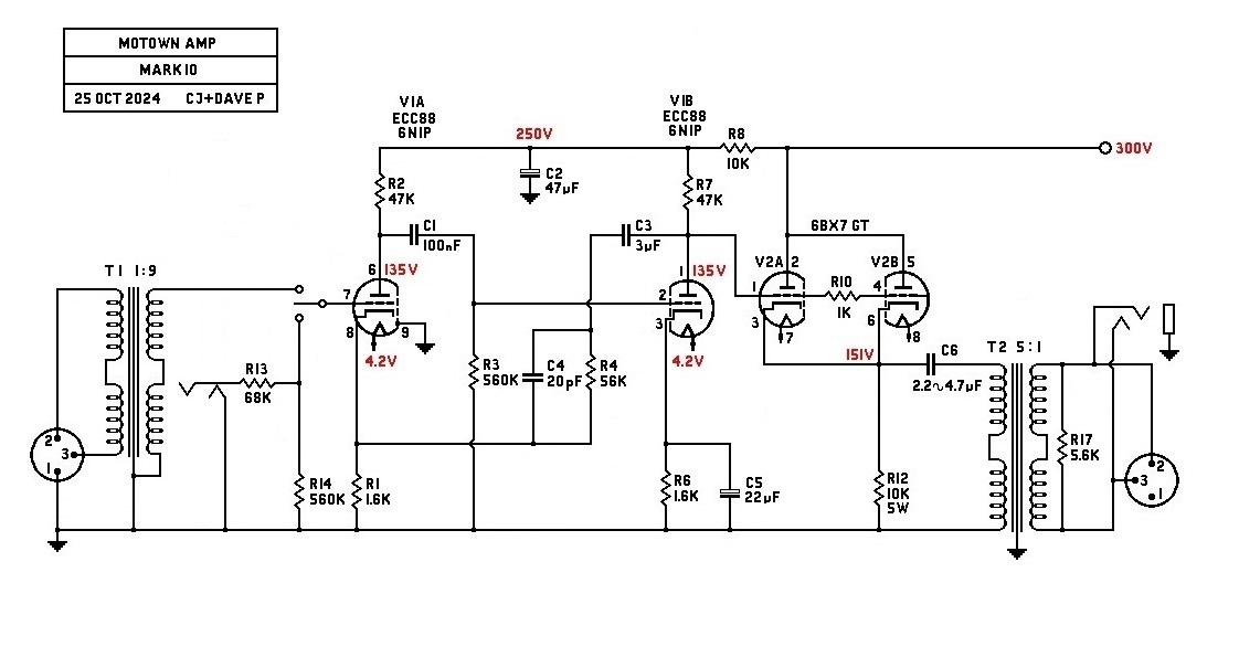
The 20 pf feedback cap and the 5.6K resistor takes care of the sq wave ringing so the 4.7K grid stopper on stage two makes no difference if it is installed or not so i yanked it out.

A bad solder joint on stage two grid resistor was not the problem causing the ringing,

The transformer primary has no effect on the scope shots for sq wave and phase shift
This was verified by doing before and after scope shots with the wire connected to the output cap or not.


Frequency response test - sine wave

at the lowest gain setting, 50% roll off occurs at 330KC KC

at the highest gain setting on the pot the roll off point is at 54KC
 
There is nothing wrong with your computer monitor.
Do not attempt to adjust the picture.
We are controlling transmission.
We will control the horizontal.
We will control the vertical.
We can roll the image; make it flutter.
We can change the focus to a soft blur or sharpen it to crystal clarity.
For the next hour, sit quietly and we will control all that you see and hear.
We repeat: there is nothing wrong with your computer monitor.
You are about to participate in a great adventure.
You are about to experience the awe and mystery
which reaches from the inner mind to "The Outer Limits".


1729827647834.png


1729828383705.png

/
 
Last edited:
Don't, worry, I am about to bolt the base plate on and call this thing good now that we have come full circle back to the original schematic,

Dave you have a good simulator, which one are you using?

FYI: open loop gain was measured at 278 before the transformer.

Somewhere down the line I might wind a SE transformer and try a class A output stage just for kicks.
 
There is capacitance between the two tubes which could cause oscillation, so R10 is there to damp that down.
best
DaveP
Well done @DaveP and @CJ !
Great job the two of you & very inspiring project.

Quick question: Is there an easy/ier to source replacement for V2 - 6BX7 GT ?
All the "equivalents" I found so far were mainly RCA USA, Tung-Sol (6BL7GT, 6DN7, 6BX7).
Not so common around here.

Thank you all for this thread.
M
 
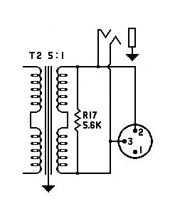
>> I'm just wondering.....since the XLR connector is "Pin-2 = High/Hot" and "Pin-3 = Low/Cold" and the TRS connector is wired as being "Tip = High/Hot" and "Ring = Low/Cold".....wouldn't that mean that the connections as shown in the schematic below for the TRS connector need to be reversed? Or.....what am I missing here?
1730305528684.png
1730305574412.png
/
 
In a related thought, the following idea was presented in the Bo Hansen 325-DI schematic. With the proper output transformer one could easily support a balanced line, balanced mic level and a variable unbalanced 1/4” output for a monitor amplifier.

If using a single secondary output transformer one could still follow this same idea if only a line, mic or instrument amp level output was desired.
IMG_6722.jpeg
 
If you know what you are plugging the DI box into, then you could configure the output accordingly. I will be going into a Mackie 16 CH board for live shows so I am going to use line level TRS jacks with a ground lift.

And a couple of 1/4" mono "Thru" jack's on the front so the guitar players can go straight into their amp. These guitar players can get paranoid about going into a DI first, so I am going to have to explain to them how their signal will not be altered in any way (don't tell them about the 1 meg input resistor to ground).

I like the options map2112 has drawn, you could possibly use the mic and line XLR's on the same secondary winding as the xfmr will probably need a load resistor to dampen any ringing. Maybe use a switch for the pad so you only have to install one XLR.
 
Last edited:
You would prefer it like this midnight?

best
DaveP
[You would prefer it like this midnight?] -- What I was pointing out in my comment had NOTHING to do with any preference of mine. I was simply stating that from what I know about TRS and XLR connectors, that the connections being made to the TRS connector had its signal phase/polarity wired in reverse to how the XLR connector is wired.....that's all. SURE!!!.....the TRS signal output would still work, but its signal phase/polarity would be reversed to that of the XLR connector. Perhaps to some people it doesn't matter to them.

But, YES!!!.....your updated schematic now shows both connectors as being wired correctly (according to current wiring convention).

I apologize for having bothered you!!! SORRY!!! I thought I was being helpful.

/
 
Back
Top