Motown Direct Amplifier-inspired Preamp?

GroupDIY Audio Forum

Help Support GroupDIY Audio Forum:

This site may earn a commission from merchant affiliate links, including eBay, Amazon, and others.
Unless we hear from CJ otherwise, this is the final schematic:-

best
DaveP
The closed circuit 1/4” output jack will effectively short out the secondary of the output transformer if nothing is plugged into it (if wired as shown).

Perhaps you intended to have pin 2 of the XLR connected to the switched connection and not pin 3?

Mark
 
I think that is a stereo jack (tip and sleeve--ring not shown) and not a switched mono jack.
Unless the schematic is "properly" drawn out to show what the designer's actual intent is, you can only -- surmise -- what the current schematic is actually showing. DaveP will either need to update his schematic to electrically show what his intent really is or, he will just need to offer an explanation of what his current schematic is actually conveying. But.....I also get your point as well!!!

/
 
did some tests with a pot in place of the feedback resistor, here are some numbers>

Output Voltage taken at output cap, not xfmr secondary, voltages are P-P values

Input: 100 mv 1 KC

Output: 10 V Gain: 100 F/B Resistance: 240K
Output: 5 V Gain: 50 F/B Resistance: 91K
Output: 3.6 V Gain: 36 F/B Resistance 56K
Output: 1.0 V Gain: 10 F/B Resistance 14K

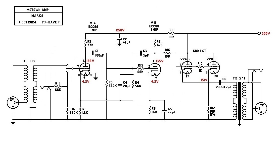
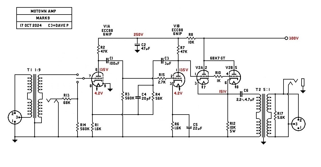
So due to some changes in grid resistors and the tube type, the F/B resistor value for a gain of 50 (34 db) is now 91K, at least on the amp that i built, this includes the 20 pf cap across the resistor.

also, with the new grid resistors, the sq wave response seems to have gotten better to the point to where the grid stopper on stage 2 is no longer needed.

i am going to use a pot to adjust the gain of this circuit from 50 to 120 so it matches the vol pot on my other amp.
 
Here are some numbers for a clipping test with various levels of negative feedback, volts P-P, 1 KC Sine Wave>


NFB Resistor: 240K Clipping at 1.6 V Input Output Voltage at cap: 120 V Gain: 75
NFB Resistor: 91k Clipping at 2.7 V Input Output Voltage at cap: 110 V Gain: 40
NFB Resistor: 56K Clipping at 3.5 V Input Output Voltage at cap: 100 V Gain: 28.5
NFB Resistor: 15K Clipping at 5.0 V Input Output Voltage at cap: 50 V Gain: 10

so gain drops at clipping level except when the resistor is at 15K which is when the most feedback voltage is applied to stage 1.
 
Back
Top