My Brain Hurts

GroupDIY Audio Forum

Help Support GroupDIY Audio Forum:

This site may earn a commission from merchant affiliate links, including eBay, Amazon, and others.
Does the modern cad automatically add bend allowances? I had some adventures at Peavey dealing with the difficulty of getting bent metal to agree with the print...

One time I gave up telling, and asked the brake operator what angles he needed to use to make a part that fit.... His bend angles added up to more than 360' and I didn't bother telling him that was impossible.  8)

JR
 
There's a bending table built in which you can customize, so yes it tells you the bendradii (although you can override them but modeling a part in a different way), but that table also has elongation values in there so you can automatically create a flat state of a part. I haven't done a ton of sheetmetal but it is a pretty nifty functionality.
The learning curve of Creo Parametric is very steep though (and it is costly software), there's not a lot you can't model with it (I have done childrens car seats, not a straight edge on there).
 
Your advancements in mechanical and electrical design are very impressive and inspiring, thanks.
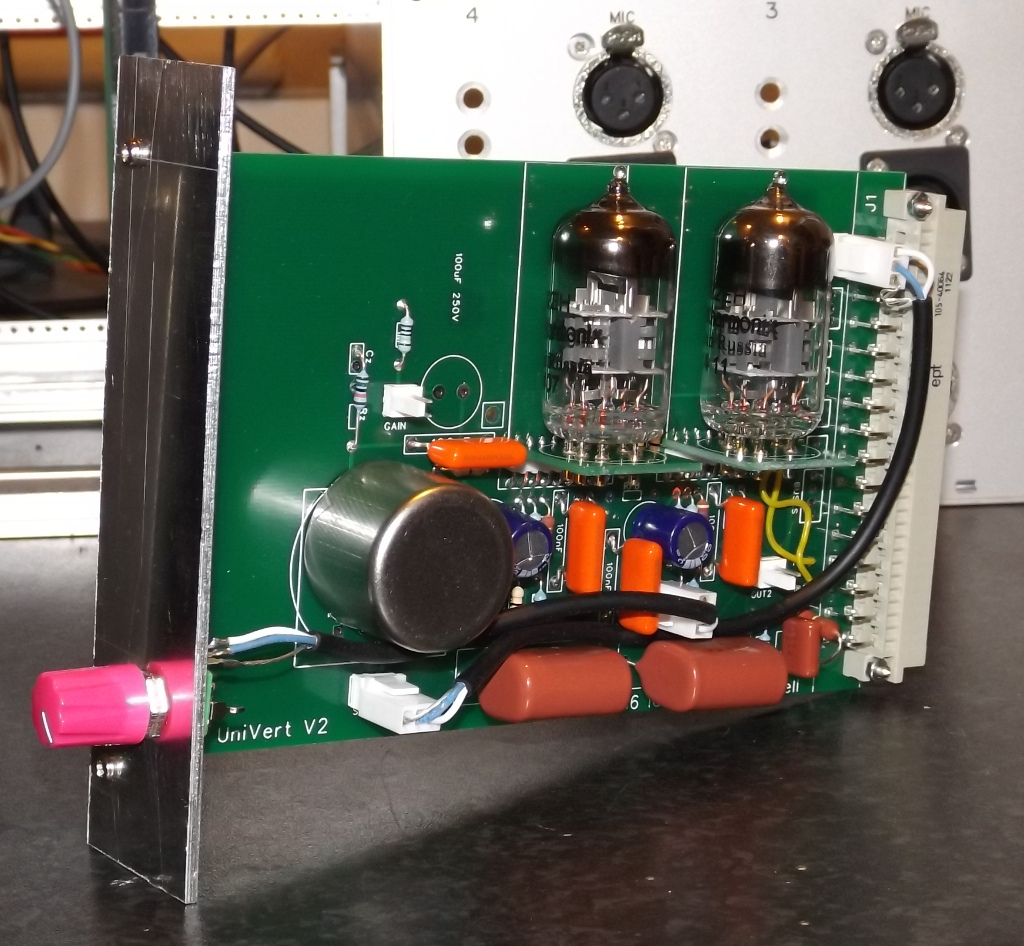
On photo 6 is Mark 3, Fischer 35,5mm module, took it as example since it is similar barinstorming:
https://mark3vtm.blogspot.si/2017/12/
Should be possible to lower input trafo and C1 if needed. That should allow for 3 tubes; similar Telefunken would have perforations at the top, while EMI with Redd modules have less space for colling E88CC, has neons... Did you try using 3 tubes, still 2? At least input tubes in mic amps often don't give much to total heat, so i guess they should be possible.
 
My3gger said:
Your advancements in mechanical and electrical design are very impressive and inspiring, thanks.
On photo 6 is Mark 3, Fischer 35,5mm module, took it as example since it is similar barinstorming:
https://mark3vtm.blogspot.si/2017/12/
Should be possible to lower input trafo and C1 if needed. That should allow for 3 tubes; similar Telefunken would have perforations at the top, while EMI with Redd modules have less space for colling E88CC, has neons... Did you try using 3 tubes, still 2? At least input tubes in mic amps often don't give much to total heat, so i guess they should be possible.

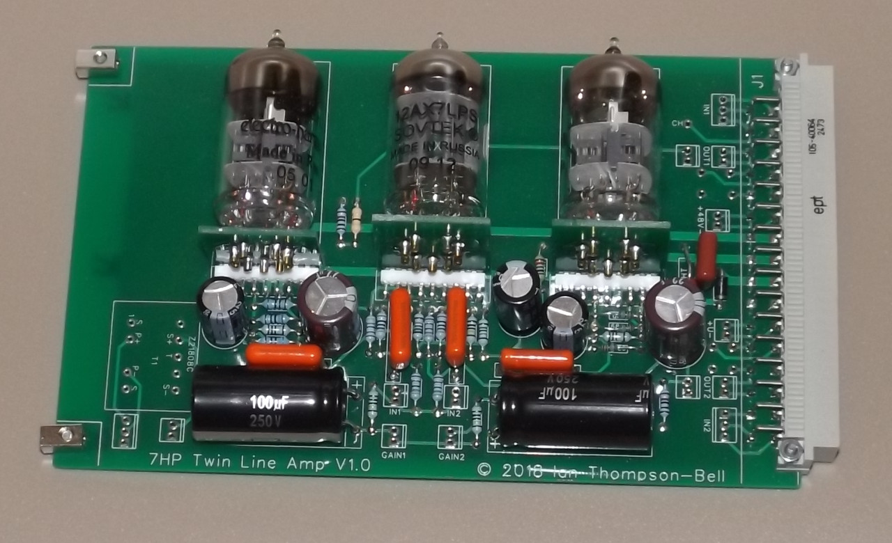
Yes I have tried three tubes. There is plenty of incentive to do this because the three tube design is so much better than the two tube design. The problem turns out to be the two 100uF 250V electrolytic capacitors that are used as part of the gain setting network. You can see the space for one of them to the left of the middle valve in the picture you referred to:

UniVertV2prototype.png


The two tube design uses only one of these but the three tube needs two. When you fit these in there is not room for the input transformer. I have designed a board like this to be used as a dual VE mixer. If I could find some radial leaded 100uF 250V electrolytics no more than 25mm high it would make more space available

A possible solution is a 6U high 35.5mm module that includes both mic pre and EQ. Then there is room to fit both an input and an output transformer. The attached PCB layout is a preliminary one that shows the basic principle.

Cheers

Ian
 

Attachments

  • Screenshot at 2018-05-07 22-44-54.png
    Screenshot at 2018-05-07 22-44-54.png
    22.5 KB · Views: 15
zamproject said:


This is weird. Lat time I did this search at Farnell, by the time I had excluded out of stock, US stock and not recommended for new designs, I got nothing. I did it again last night and got half a dozen hits. I even found a 180uF 250V from Wurth that is good for 12000 hours at 105 degrees. I ordered ten. Heaven only knows how I convinced myself these were not available.

Cheers

Ian

Edit: Even weirder, I did the RS search this morning and came up with only one  result (RS lists it as two but it is just different quantities of the same part.)
 
yes weird ?

I just check again for 100u + 250v + H25mm + 105° + 10000h and still have 8 return (in fact 4 product with different pakage qqt)

anyway those capacitor exist so you'r fine

Best
Zam

 
If some hardwiring isn't a problem you could gain even more space. I don't see a problem considering tube mixer doesn't have that many channels. If pcb goes into 2U rack it makes even more sense because 3 tubes should be good for 2ch mic amp or similar.
Do you find Molex connectors unreliable in the long run as a few others do? My approach is just hardwiring (p2p) connections like this, although i can't say for sure Molex would start having problems after 5, 10 years.
We all miss capacitor dimensions, sometimes Farnell has problems with search and i find correct ones just before ordering...
 
JohnRoberts said:
Does the modern cad automatically add bend allowances? I had some adventures at Peavey dealing with the difficulty of getting bent metal to agree with the print...
All metalworkers I worked with told me not to bother; they just want the finished dimensions and do their own receipe. The old formulae I learned at school don't seem to work anymore, considering new materials (zinc-electro-protected on grinded steel) and new tools (CNC brakes).

One time I gave up telling, and asked the brake operator what angles he needed to use to make a part that fit.... His bend angles added up to more than 360' and I didn't bother telling him that was impossible.  8)
Maybe a communication problem? Indeed, to make a 90° bend, the brake must be set at something between 95-100, so a full closed square ads up to 380-400°.
 
Just to put the problem into perspective, here is a pic of the 35.5mm version of the Twin Line Amp. You can see where I squeezed in a small OEP transformer just as a test. At the bottom you can see the two 100uF/250V caps on their backs taking up a lot of board space.

7_HPTLAV1a.jpg


Cheers

Ian
 
abbey road d enfer said:
All metalworkers I worked with told me not to bother; they just want the finished dimensions and do their own receipe. The old formulae I learned at school don't seem to work anymore, considering new materials (zinc-electro-protected on grinded steel) and new tools (CNC brakes).
Maybe a communication problem? Indeed, to make a 90° bend, the brake must be set at something between 95-100, so a full closed square ads up to 380-400°.

JR
Indeed my adventure happened before Peavey hired their first full time mechanical engineer so the buck stopped with me for that one.  After we had a mechanical engineer I let him deal with the bend details. But there was always drama with bending metal. We used some weird vinyl coated sheet metal, that used special brake tooling to not tear the vinyl, so even the bend allowances were not standard.

The particular metal that didn't add up to 360'  was an odd shaped chassis for a foot pedal that had to fit molded plastic endbells.  I think I just gave the guy some endbells and said make it fit. But it didn't take long, for the plastic endbells to get worn down to fit into incorrect bent metal, causing grief at the final assembly production lines. 

JR
 
My3gger said:
If some hardwiring isn't a problem you could gain even more space. I don't see a problem considering tube mixer doesn't have that many channels. If pcb goes into 2U rack it makes even more sense because 3 tubes should be good for 2ch mic amp or similar.
Do you find Molex connectors unreliable in the long run as a few others do? My approach is just hardwiring (p2p) connections like this, although i can't say for sure Molex would start having problems after 5, 10 years.
We all miss capacitor dimensions, sometimes Farnell has problems with search and i find correct ones just before ordering...

I often hardwire but do allow space for Molex connectors. They are very useful for front panel connections and invaluable when troubleshooting as it allows you easily to isolate sections or inject signal half way down a circuit.

There are other issues to contend with. The rear of the PCB is a ground plane. I try to avoid tracking on that side as much as possible for obvious reasons and at the same time I want to avoid links. The tubes need to be separated for adequate air flow to each and I want to avoid placing components near them.  The area to the left is needed to accommodate front panel controls so only low profile components like resistors can go there. I think replacing the two 100uF/250V caps will free up a lot of space and I might just be able to squeeze in a Cinemag.

Cheers

Ian
 
JohnRoberts said:
We used some weird vinyl coated sheet metal, that used special brake tooling to not tear the vinyl,
So do we; significant cost savings since the product does not need any other finish than the nice zinc treatment. The metalworker knew he had to adapt to this.

The particular metal that didn't add up to 360'  was an odd shaped chassis for a foot pedal that had to fit molded plastic endbells.  I think I just gave the guy some endbells and said make it fit. But it didn't take long, for the plastic endbells to get worn down to fit into incorrect bent metal, causing grief at the final assembly production lines. 
Tools get worn out, materials change... Hence the need for a golden sample. [sigh]
 
mjrippe said:
Ian, are you soldering the tubes straight to those daughterboards or are there pin sockets I am not seeing?

to me it look like individual pin socket like we see for various DOA

side note for Ian, about the angled tube mount, maybe having a mechanical holder at the top might secure the tube and the connector soldering to main PCB, I guess just two hole (or better pad) to attach a rilsan or solder a wire.

best
Zam
 

Attachments

  • secure_valve.jpg
    secure_valve.jpg
    190.3 KB · Views: 15
zamproject said:
side note for Ian, about the angled tube mount, maybe having a mechanical holder at the top might secure the tube and the connector soldering to main PCB, I guess just two hole (or better pad) to attach a rilsan or solder a wire.

best
Zam

It is not usually necessary to secure the tubes for normal operation. They are a tight fit in the socket. and there is normally a steel screen that completes the module as shown here:

7_HPclassic_Top.jpg


For shipping it is easy to wrap a short length of bubble wrap around the tube and instruct the end user to remove it before plugging in the module. The distance between the top of the PCB and the steel screen is 26mm and the tubes are 22mm nominal diameter. I have toyed with the idea of fitting them with a high temperature grommet O ring.

Cheers

Ian
 
ruffrecords said:
I often hardwire but do allow space for Molex connectors. They are very useful for front panel connections and invaluable when troubleshooting as it allows you easily to isolate sections or inject signal half way down a circuit.

There are other issues to contend with. The rear of the PCB is a ground plane. I try to avoid tracking on that side as much as possible for obvious reasons and at the same time I want to avoid links. The tubes need to be separated for adequate air flow to each and I want to avoid placing components near them.  The area to the left is needed to accommodate front panel controls so only low profile components like resistors can go there. I think replacing the two 100uF/250V caps will free up a lot of space and I might just be able to squeeze in a Cinemag.

Cheers

Ian

Yes, those 100u caps could be smaller. Even 2ch 2U allows for L profiles and turret boards where caps can be far from any heat source. Of course consoles are another thing. Thanks for showing tube mountings, sometimes people ask me how to do it properly on pcb...
 
mjrippe said:
Ian, are you soldering the tubes straight to those daughterboards or are there pin sockets I am not seeing?

I was wondering the same thing. That might be the lowest profile PCB tube socket method I've seen before the turning the card sideways on a daughter board.  :D

For shipping it is easy to wrap a short length of bubble wrap around the tube and instruct the end user to remove it before plugging in the module.

Don't use bubble wrap around the outside of new products though - it stains some paints
 
Back
Top