


owel
Well-known member
It's finished... I decided to put 4 channels of my SC-1 mic preamp kits in a half-rack case.
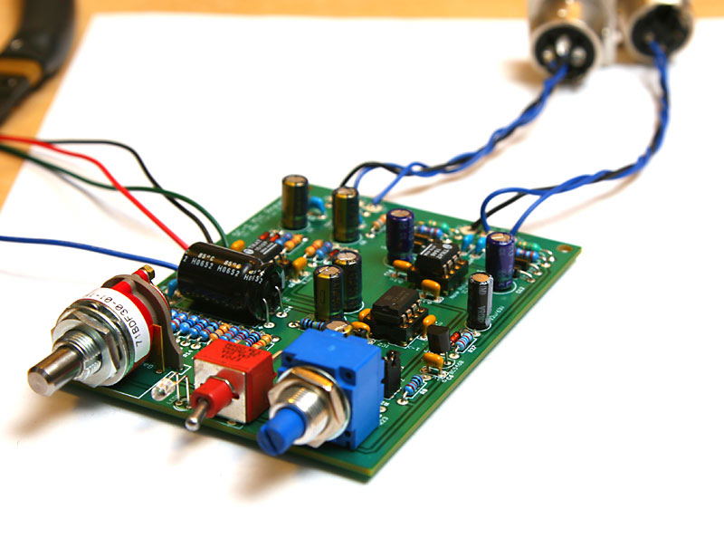
The preamp is a THAT 1510 based pre, with DC servo using Burr Brown chip and THAT 1646 balanced line driver. (See my sig for more info)
It's got soft-start phantom power... so no loud thudding/popping when you turn on/off phantom power. Using THAT chips, Burr Brown chips, Grayhill switches, Bourns pot, C&K switches, gold-plated machined IC sockets, Panasonic caps, C0G NPO, metal film, RFI input and output protection, diode/zener input and output protection, Neutrik XLRs, etc...
Frequency response I got using TrueRTA software is here.
http://www.fivefish.net/diy/sc1/images/SC1quicksweep.gif
I have a kit builder compare it's sound to the DAV, and find this pre more open and clearer. Another calls it with "miles and miles of gain"... at +72dB (i.e. +66db from preamp + 6db from balanced driver). It's basically clean, crystal clear, lots of gain, quiet, low noise.
Some photos:
The SC-1 Kit:

4 channels in one 1/2 rack case.

The PWR-TRAFO and PWR-CONTROL Kit in use... 25VA transformer assures plenty of power to power up 8 channels!

Top View. Pretty tight.

Back panel, showing the XLR input and output jacks. Decal was also used for the back panel.

The Front view... I'm trying out different knobs... the front panel was also created using decals.

The preamp is a THAT 1510 based pre, with DC servo using Burr Brown chip and THAT 1646 balanced line driver. (See my sig for more info)
It's got soft-start phantom power... so no loud thudding/popping when you turn on/off phantom power. Using THAT chips, Burr Brown chips, Grayhill switches, Bourns pot, C&K switches, gold-plated machined IC sockets, Panasonic caps, C0G NPO, metal film, RFI input and output protection, diode/zener input and output protection, Neutrik XLRs, etc...
Frequency response I got using TrueRTA software is here.
http://www.fivefish.net/diy/sc1/images/SC1quicksweep.gif
I have a kit builder compare it's sound to the DAV, and find this pre more open and clearer. Another calls it with "miles and miles of gain"... at +72dB (i.e. +66db from preamp + 6db from balanced driver). It's basically clean, crystal clear, lots of gain, quiet, low noise.
Some photos:
The SC-1 Kit:
4 channels in one 1/2 rack case.
The PWR-TRAFO and PWR-CONTROL Kit in use... 25VA transformer assures plenty of power to power up 8 channels!
Top View. Pretty tight.
Back panel, showing the XLR input and output jacks. Decal was also used for the back panel.
The Front view... I'm trying out different knobs... the front panel was also created using decals.


