My version of the THAT1512 Pre

GroupDIY Audio Forum

Help Support GroupDIY Audio Forum:

This site may earn a commission from merchant affiliate links, including eBay, Amazon, and others.

ricothetroll

Well-known member
Joined
Jul 5, 2005
Messages
325
Location
Bruxelles
Hi,
I drew this version for a friend, who wanted a clip indicator and a HPF.
Here are the files :
https://dl.dropboxusercontent.com/u/28610725/Schem_v3.png
https://dl.dropboxusercontent.com/u/28610725/Board_v3.png
Any comments will be apreciated ! I'll post the copper layer once the circuit will be built and tested good.
Best regards.
Eric
 
Hi,
Yes it did work out !
Still not in a box though because I'm still waiting for a custom made trafo (made for low flux) to end the project. Since, I forgot to put the copper layer here... Sorry
Here is the copper layout :
https://dl.dropboxusercontent.com/u/28610725/THAT1512_Preampp_v3_x3.brd.pdf
If you want to give the circuit a try I have a PCB of 1 preamp left : I printed 3x3 PCB, each on a 160x100mm board, but needed only 8. It only needs to be drilled. I could give it away and send it to the Netherland for like 5€ I guess.
Best regards.
Eric
 
Hi,
I'm currently building an 8 channel version of this THAT1512 preamp.
I have an interrogation though : is it necessary to use shielded cable from the PCB to the gain setting pot ? As there's like 15cm of cable from the PCB to the front panel, I wonder if the impedance of the Rg1-2 connection of the THAT1512 is high enough for presenting a risk of acting like an antenna for the mains trafo hum (I'm using a custom made  toroidal trafo designed for low flux, 300V->2x20V to be used as a 230V->2x15V).
Any thoughts about it ?
Best regards
Eric
 
Actually the gain adjust can be a super low impedance, but can be upset by small stray capacitance, or the inductance of long wires.

I'd want that wire much shorter than 6 inches.
 
Hi PRR,

Thanx a lot for your answer !

Actually the gain adjust can be a super low impedance, but can be upset by small stray capacitance, or the inductance of long wires.

All my PCBs are now etched and populated, so I guess I just have to try and see if troubles do happen  :-\

So I guess stray capacitance causes a gain increase at HF and inductance at LF. For capacitance, I calculated that at 11MHz, with a 10pF stray capacitance, there's about 1k5 in parallel with Rg, that's 12dB. As 11MHz is the -3dB fc, that's a gain of 9dB. Is that something I should fear of ? For stray inductance I have no idea of what range it can be at...

Best regards.

Eric
 
I haven't dealt with this for a few decades and back then I had more options. My preamp used discrete transistors in front of op amps, but a very similar topology to the 1512. With access to the gain stage op amp outputs you can connect the shield(s) there and instead of looking like C to ground, now it looks like feedback C.  ;D

My first concern was stability (freedom from oscillation), next HF CMRR,,, If the C to ground at both ends of the gain cap are different the HF gains won't match and cancel out HF noise as well.

Given your limited options, first just try is and see what happens. (My old console had more than 15cm of shielded cable. ). Of course use low capacitance cable....If even that is not low enough, twisted pair may provide enough cancellation of magnetic interference.

Good Luck

JR
 
Hi there,

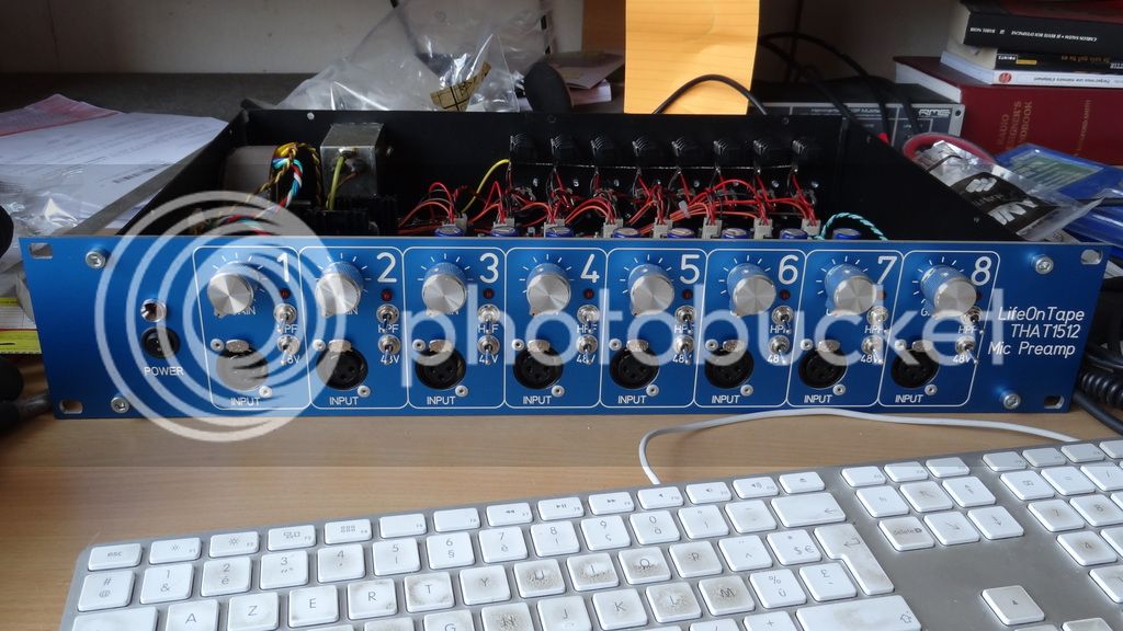
I finally finished building the preamps. I chose to do an 8 version of it.

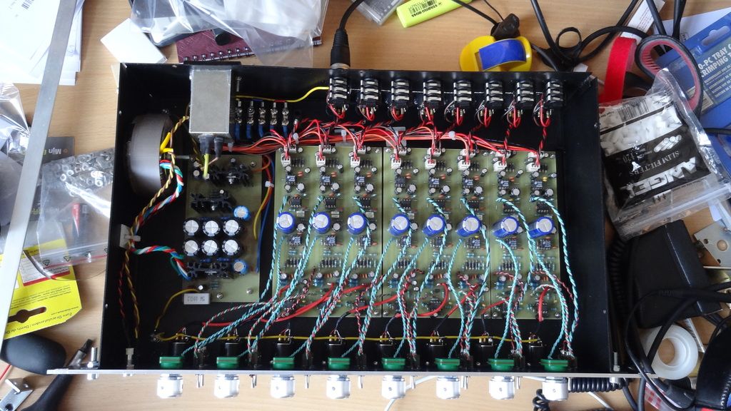
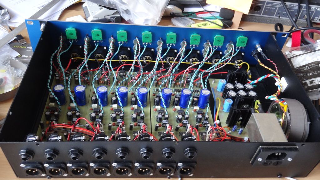
Here are some pics of the result :

DSC02945_zpsvmnedygu.jpg

DSC02944_zpsaqsw7jk1.jpg

DSC02946_zpspxvcsocx.jpg


The only thing I'll add is an aluminium bar to attach the wires that connect to the front panel, to relieve the weight on the solders.

Now, some post-build thoughts/comments/interrogations :

- That was a lot of work to build, especially because of all the air wires to the front panel. Although it works perfectly, if I had to do it again I'd make another layout with vertical/double width PCB, switches and pots soldered to it, with care taken not to hace the PCB forcing on the solders.

- Building with vertical and larger / less deep PCBs would allow to move the trafo further away from the preamp circuit, which is always a good thing to avoid magnetically coupled hum.

- Talking about mains trafo, I had a custom low-flux trafo made by Audiophonics (300V->2x20V used with 230V input). With this trafo inplace, at the same place as the current one, the 50Hz hum was buried deep in the hiss, but I had some 150Hz + harmonics stronger than the hiss. This was with 150R resistor across the mic input and the gain all the way up. I first suspected some radiations from the rectifier but it finally appeared that it came from the trafo. I did some tests with a small but thick ungrounded piece of steel, and it could cancel the noise when put in some precise places, though not practical to install permanently. I also tried to deport and move the rectifier without any effect. I then put another trafo I had in stock, and the 150Hz noise disappeared completely !
I don't understand why the custom trafo leaded to more noise, maybe fed back from the rectifier. The only noticeable difference is that it has a screen between primary and secondary, and the one I kept hasn't. There might be some differences in wrapping pattern but I don't have access to those infos ;)

- The preamp is dead silent and has a very flat response.

- I had to wrap the trafo with laminated steel to completely bury the hum into the hiss.

- The power inlet + filter is a Schaffner FN 362-2/05 I had in my drawer. I don't know how useful this is, but I guess it could help keeping the noise down in case of dirty mains. There's 2x5,3mH in series, 2x0,1uF across the line a,d neutral, one before and one after the inductors, and 2x2200pF between line/neutral and earth.

- The output drivers are THAT1646. In some "bad case scenario" test I fed the preamp with a different mains circuit from the RME Multiface soundcard that receives the signal, and I had a STRONG hum ! It could be cured with an isolation transformer, and lifting ground has no effect on it. Could it be due to a mistake I've made ?

- Grounding is done that way : Earth connected to the case, Pin 1 (in&out) connected to the case, audio ground connected to the trafo CT and the trafo CT is connected to the case via 10R/5W // 100nF // 2x1N4007.

- Case engraved by Schaeffer.

That's all ! Please share any comment or critic.

Best regards.

Eric
 

Latest posts

Back
Top