Needed: dbx 157 schematics

GroupDIY Audio Forum

Help Support GroupDIY Audio Forum:

This site may earn a commission from merchant affiliate links, including eBay, Amazon, and others.

joe-electro

Well-known member
White Market Member
Joined
Jun 5, 2006
Messages
502
Location
Somewhere doing audio stuff.
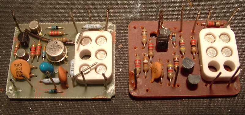
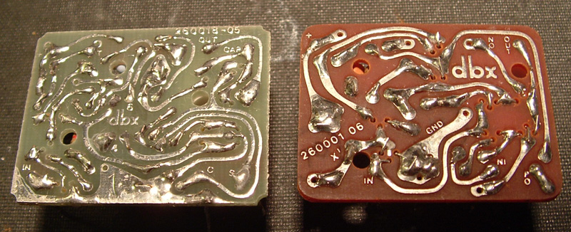
I found an old dbx 157 Noise Reduction unit in the garage today while I was looking for something else. It has a bunch of non-descript metal cans in it, similar to dbx 202 VCA's but with a different pinout and footprint. I'm just wondering if those cans could be used to build a cool compressor. Seems like a reasonable possibility.

Anybody got schematics on this thing?

Thanks!!!

-- Joe
 
[quote author="mediatechnology"]No, not exactly for the 157

But there is this site: ftp://ftp.dbxpro.com/pub/PDFs/discontinued/Schematics

Didn't have any 157 schematics but perhaps some other vintage product uses the same devices. Would one of the cans be the rms detector?[/quote]

Yeah, I went to this site first and drained it dry. Lots of good stuff but nothing about the 157. I guess it had been discontinued before Harmon bought dbx.

The problem is that there is no silkscreen layer and no part numbers. I could guess the function of some of the cans (there are seven silver and one black one) based on other units but the only way to know for sure would be to have a schematic and possibly a parts layout.

Thanks,

--Joe
 
[quote author="mediatechnology"]
I'm thinking that since what you have is a stereo noise reduction unit, with simultaneous encode/decode, is that you have 4 VCAs and 4 RMS detectors. That would make 8 cans. One of them was probably a replacement.[/quote]

I think you're right. I desoldered all the cans last night and guess what - no epoxy! The circuit boards are held in by one solder joint and a little bit of hot glue. There are two different styles of boards, the first one marked "260001 06" and the second marked "260018-05", both sporting the dbx logo. I pulled the boards and will post some porn of them later today hopefully.
 
[quote author="mediatechnology"]The VCAs may have two transistors held together with a white Beryllium-ceramic collar. These would be the VCA matched pair IIRC.

FYI: Try not to ever chip Beryllium as the dust is toxic if inhaled.[/quote]

Okay, here's some porn:
157modules-1.jpg

157modules-2.jpg


I'm betting the brown board is the VCA and the green board is the RMS level detector and log/linear converter. What do you think :?: :?: :?:
 
[quote author="mediatechnology"]I think it may be the other way 'round. VCA may have five transistors; rms four. [/quote]

Curiosity is killing me; I'm going to have to trace out the circuit for both boards. I'll post the schematics ASAP. BTW, what's the original patent number? Thanks!!!
 
[quote author="mediatechnology"]They are:

http://www.ka-electronics.com/Images/Blackmer_Patent_3714462.pdf

http://www.ka-electronics.com/Images/Blackmer_RMS.pdf (3681618)

Have fun![/quote]

Thanks!!!
 
Back
Top