Neve 1073 EQ out patch point

GroupDIY Audio Forum

Help Support GroupDIY Audio Forum:

This site may earn a commission from merchant affiliate links, including eBay, Amazon, and others.

dogears

Well-known member
Joined
Nov 15, 2017
Messages
548
Location
Texas
Hi guys. I was looking at the 1073 schematics online and chatting with a buddy. There are some pieces of information I’m having trouble reconciling. Maybe y’all can sort me out?

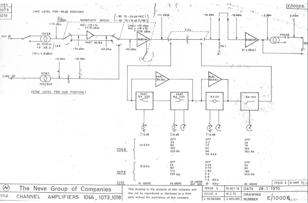
The EQ out send is listed as -18 dBm on the channel amplifier block diagram. There’s also no explicit EQ out point on the detailed schematics. My friend has worked on a Neve desk and says there’s a balanced EQ out and Fader in point on the patchbay. However, he says that if you take a signal from the EQ out patch point and the same signal from the direct out with the fader at unity, the level is the same.

I’m not sure I understand that.

Also, if the EQ out and fader in are balanced, where are these transformers located? They’re not on the schematic. And does the insert send have a line amp? He mentioned once splitting a signal four ways to various gear. So the idea of no line amp or a step up transformer seems doubtful.

Any help?
 
In a Neve desk the insert point is taken from the output of the 1073 module, and the return is the input of the routing module.
Some routing modules also has a post fader insert,  thay have 3 transformers inside.
You could make a unbal -18db insert point in a 1073 at the eq bypass point. But remember the eq wants to see a 5k load.

Best
J
 
Hi Joe,

Thanks I think that clears it up. I was under the impression that the fader was before the line output amp instead of after the output transformer.

So on this diagram (from here) what does the out/back arrow after the 5K1 load resistor represent?

CNH5Pah.png


Thanks!!

 
That should be pin K and L on the connector. I think Neve used this insert point for a fader in one of the small Neve consoles.
It migth be linked on the inside of the connector...
 
As it says in the manual, this link was provided to allow a 5K fader to be used instead of the 5K1 terminating resistor in low cost consoles. It was never intended as an insert point.

Cheers

Ian
 
Gonna resurrect this thread with another question. Is the 4 dB drop across the EQ indicated on the block diagram correct? If so, what’s the rationale for that?
 
Ok, figured it out. When the EQ is in, there is a 4 dB drop due to the passive design. When the EQ is out a 2k7 resistor is switched in for the same drop. So the drop is there, but not additional when the EQ is in.
 
dogears said:
Ok, figured it out. When the EQ is in, there is a 4 dB drop due to the passive design. When the EQ is out a 2k7 resistor is switched in for the same drop. So the drop is there, but not additional when the EQ is in.
Actually most of the 1073 EQ is active (certainly the sections with boost are). The only passive part is the HPF which comes last. The 4dB loss may occur there.

Cheers

Ian
 
ruffrecords said:
Actually most of the 1073 EQ is active (certainly the sections with boost are). The only passive part is the HPF which comes last. The 4dB loss may occur there.

Cheers

Ian
I also assumed it came from the passive circuit... but it doesn't, surprisingly enough. Each active contributes some.

Attached shows the level with the controls centered and LF / MF set to off after stage 1 (HF and LF shelf) and after stage 2 (MF level).

AAPGoA6.png


Also interesting... with the level pots set to middle the frequency response is definitely not flat with a LF or MF frequency selected. I suppose with this kind of circuit that's to be expected, but it's pretty not-flat.


interesting. the response shold be flat at the electrical centre of the pot which may no coincide with the physical centre. you might like to try tweaking each pot slightly to see if there is a flat position. the other problem with active circuits like this is that flatness depends on the tolerances of the boost and cut caps. These are often very different values and small differences between them can a difference at frequency extremes.

Cheers

Ian
 
ruffrecords said:
interesting. the response shold be flat at the electrical centre of the pot which may no coincide with the physical centre. you might like to try tweaking each pot slightly to see if there is a flat position. the other problem with active circuits like this is that flatness depends on the tolerances of the boost and cut caps. These are often very different values and small differences between them can a difference at frequency extremes.

Cheers

Ian

Hi Ian,

This wasn’t a test plot, just a simulation of the circuit. So everything is ideal.
 
dogears said:
Hi Ian,

This wasn’t a test plot, just a simulation of the circuit. So everything is ideal.
Hmmm. So the top line is after one stage and the bottom one after two. looks OK up to 1KH but in both case theHF drops off more than I would expect. Can you post the sim file?

Cheers

Ian
 
Hi Ian,

I think I forgot to save it, so I re-drew it. I may have had a typo in a capacitor value somewhere, because I don't get quite the same response. Attached is the re-draw, double checked this time and tried to label the various connection points on the cards for clarity. I changed the filetype to .jpg, so rename it to .asc for LTSpice.

At any rate after the first stage you lose about 1 dB at 1kHz, after the second youre at -2dB at 1kHz, and all the way through you end up at -4dB at 1kHz.

Interesting to note that there is a very gentle ~1.5 dB rolloff from 10k-20k and a very slight push at 3kHz with the EQ in, HF set to flat, MF and LF set "off" and the HPF set "off". I've often heard of people saying this EQ sounds better switched in even if not used - have to wonder if these minor changes plus whatever THD you get from the two gain stages have something to do with that.


Attachments

  • 1073EQ.jpg
    19.8 KB · Views: 28
ruffrecords said:
Are you sure about the off connections for the hf shelf?

Cheers

Ian

Haha, well when you ask like that, no.

But I double checked, I think I have it right. Using the schematics posted here:

https://www.technicalaudio.com/neve/neve_pdf/1073-fullpak.pdf

Do you see a mistake?

It's interesting that the BA284 gain blocks do not hit their maximum gain of ~50 dB until around 1k. The 480p and 180p feedback capacitors seem to be there to adjust for this by rolling off some HF.

It's a bit interesting to replace the 480p with something like 680pF cap in series with a 39k resistor // 82pF  and making the second feedback very small cap. Flattens out the high end to within .1 dB.
 

Latest posts

Back
Top