Neve 1272 mic pre clone PROBLEM

GroupDIY Audio Forum

Help Support GroupDIY Audio Forum:

This site may earn a commission from merchant affiliate links, including eBay, Amazon, and others.

Palmito

Member
Joined
May 7, 2010
Messages
17
Location
Nice, Fance
i'm new to this forum, and also to electronics, so please forgive me if some of my questions seem stupid...

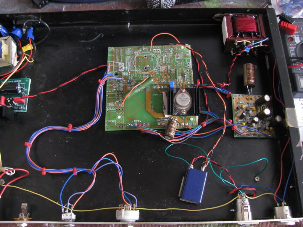
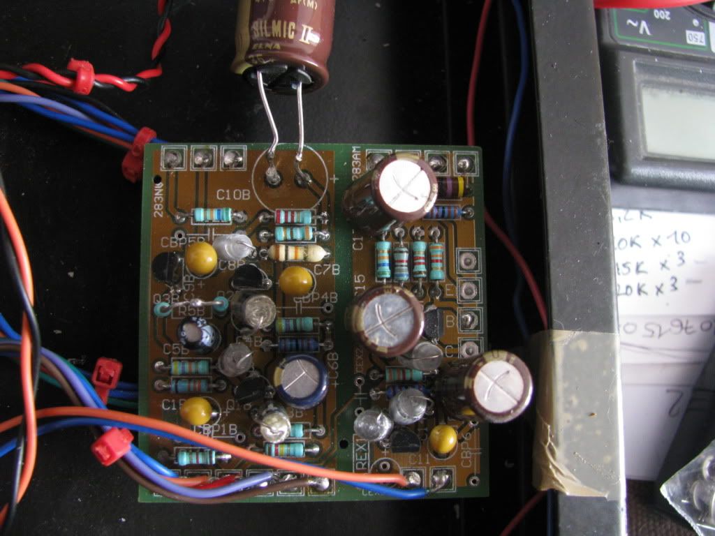
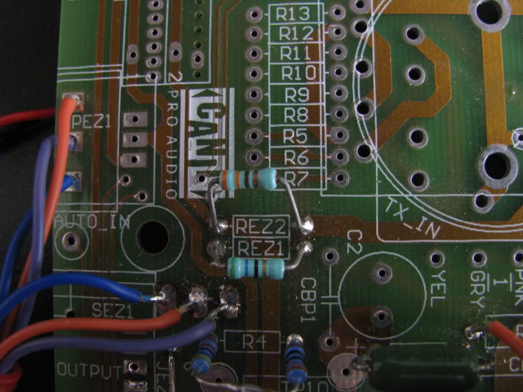
i bought a few months ago a DIY NEVE 1272 clone mic pre based on Canill pcb's. (N72 & 283N)
They are not available anymore but still appear on braudio's website, here's the link: http://www.braudio.com/products.cfm?view=Product&ItemCode=CAN72PCB

The guy who sold it to me told me it was working, and only the transformers (carhill VTB9045 & VTB4049) needed  to be secured in place. Apparently i can't find any visible problem, no shorts, the guy seems to have made a good job, but...

Here is my problem:

at low gain settings, everything works fine, but as i raise the gain up, there's a point at which there's no more audio on the output, and it looks like there's some kind of short, as i see the vu's from my converters go all the way up, like if there was a big DC or something... I don't like this !

Another strange thing is that i can hear a big fuzzy sound coming out of the output transfo !! Man this is weird !!

From what i know about mic pre's, this particular one is a 2-stage (correct me if i'm wrong!), so my guess is that the problem comes from the second stage of the preamp, as it appears when i raise the gain up.

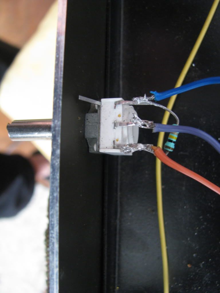
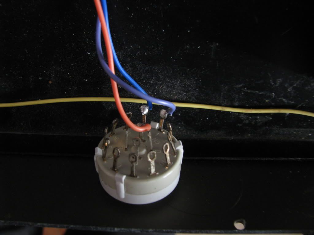
When i test the output transfo, i find that all the pins which are on the same side (1 to 4 and 5 to 8) are all connected. Is this normal or is the outup transfo faulty ?

I totally new to this so i need your help guys !

Do you think my guesses are right ? Do you know any way of testing the output transfo / preamp ? 
I don't know if the pre was build correctly, or if any part is faulty. So i hope you guys that know about audio electronics can help me...
i can post pictures if it can be of any help...

thanks in advance !!

Alex
 
Any pics?  Possibly your transformers are too close to each other? (high freq oscillation)

A good thing to do (assuming you haven't got a scope) is to build a simple signal probe. (if you do a search, you'll find the plans.)  This will allow you to trace along a circuit, finding at where the signal 'gets off the train'.

Confirming how the gain switch is set up also would be a good idea.  In a 2 stage clone, both stages (an input and an output stage) are always in circuit.  With most of the different gains being set by the use of pads just after the input traffo.
 
It seems like every BA283-ish Neve clone has the gain staging done differently.

So that would be the part I would look into next, just as onlymeeee says.

Because it's working at the lower switch settings, something could be wrong with how the "gain" switch is connected.

Can you post pictures and/or trace out how the switch is wired up to the rest of the circuit?
 
This might help you out.. The schematics for your 1272 clone are probably on the following page:

http://www.thediypill.phx.com.br/forumfiles/

This page has most of Fabio's (Canil) stuff..

Good luck!

-jay
 
you guys rock !

my board is rev2 version, i finally found the shematics and an FAQ page  ( http://www.thediypill.phx.com.br/neve/m1272.html )

the builder of my unit skipped some elements (48V, phase switch, DI input...) and i believed he made the EZ mod, as i have 1 pot for gain + a 2-position switch...

so now i have to compare my pre to the schematics, and see what i can understand... Not easy for me !

if you have other ideas... anyway i'll let you know how i'm doing and will post pictures soon.

thanks !!
 
is it possible to swap the amp cards? IF the problem follows then it's in the amp card that ba-283. If the problem does not follow then you can look elsewhere. Start big and go small. Eventually you will find the issue
 
i can't switch my ba283 card since i only have 1 (N7290 rev1 pcb)

i did some more testing, move the transformers around and add one ground cable to the output xlr. less noise, but same problem.

so my pre has the ez mod, so only a 5K log pot for gain, and a 2 pole switch (which switches between 45 and 60 db of max gain)

everythings ok with the switch on the "low gain" position , but the problem occurs when i switch this gain selector.

so i believe my problem comes from this part

but looking at it on the schematics ( http://www.thediypill.phx.com.br/forumfiles/m1272_sch_rev2.pdf ) , i can't figure how it work, what it is doing to the signal...

i need to understand this part of the circuit if i want to fix my problem...

so maybe someone can explain it to me...

thanks in advance ! i think im getting close
 
Try adjusting the bias of the output stage.
There should be a 5K trimpot; looks like it's labeled bias on the board right near the 2N3055 (QS1).
It helps to have a scope so that you can see what's happening on the output.

I don't know that this would be the cause of your problems, but you might as well check it.
 
Have you got a multimeter?  Would be handy to get some voltage measurements.
After checking your 24V rail, check what voltage you have on the case of the 2N3055 transistor. Would give an idea of whether you're set up roughly correct on your output stage.  Careful you don't crank the bias trim pot completely too much 'one way' or you can draw too much current and a couple of resistors will start getting excited
 
I  checked the voltages, so heres what i got:

my 24V rail is 25,4V. Is that OK ? the psu is a Velleman Kit. Does the small trimpot on the psu board adjusts the output voltage ?

then i tested the voltages at the transistor pins (2N3055).

-between the 2 pins i have 0,05V, 
-between 1 pin and ground i have 22,4V,
-between the other pin and ground i have 23V.

What is weird is that when i switch the "gain selector" (rez1), these voltages drop down to around 15V.

Once again, my problem appears when i switch rez1 to "hi-gain" , so i'd like to understand what this switch does to the signal.
Does it switches the signal to a different part of the 283, like switching from one stage to another ?

I really need to understand this in order to know where to look for a problem !
Could someone explain this to me, as when i look at the schematics, i can't figure how this REZ1 works...
 
just another question,

i cant figure out which are the pins of the 283 pcb. On the schematics they are labeled 1A, 1B... to 2J.

but these nombers dont appear on the board ...

Anybody knows how i can figure this out ?
 
i took some pictures

this is the gain pot
IMG_5945.JPG


the REZ1 gain switch
IMG_5938.JPG


gain wiring
IMG_5937.JPG


the whole pre
IMG_5940.JPG


the 283 board
IMG_5943.JPG

only 3 pins are marked (E, B, C)

i dont know if the pictures will work, if not, how can i post pictures on this window ?
 
Palmito said:
I really need to understand this in order to know where to look for a problem !
Could someone explain this to me, as when i look at the schematics, i can't figure how this REZ1 works...


On the BA283, you can easily change the gain of the first stage by connecting a resistor between pin T and ground.
This is what your 2 position switch is doing.
If you leave this connection open, you have a fixed gain of around 18dB.
To increase gain, change the resistor.
330R = 23dB
120R = 28dB
56R = 33dB
27R = 38dB
12R = 43dB
8.2R = 48dB

Your switch has two settings, 330R and 30R (330R + 33R in parallel).


What's your grounding scheme like?
The audio ground should be connected to the power supply ground at one point only and tied to chassis at this point, preferably the AC ground.
 
ok thanks

i tried to adjust the bias trim pot, it doesnt seem to change anything...

now my problem is to figure where is pin T on the 283...

so here are the pictures

TOP VIEW
IMG_5940.jpg


283
IMG_5943.jpg

only pins E, B and C are labeled, does anybody know how i can figure where are all the pins ?

GAIN WIRING
IMG_5937.jpg


GAIN POT
IMG_5945.jpg

its marked 4,7KL, so i think the resistor is supposed to make the pot logarythmic, right ?

REZ1 GAIN SWITCH
IMG_5938.jpg


The fact that the voltage drops when i switch REZ1 switch is normal ? Its seems strange to me...
 
1) That's a sloppy build if ever I saw one (no offense to the builder—we've all done it).

2) The "BA283" board looks like it's just sitting on the chassis. Elevate that puppy with standoffs...same thing with the Power Supply PCB.

3) Personally, I would, remove all of the electrical tape and reconnect all of the wiring with heatshrink.
Use this image for info on grounding Nevey circuits and where to use shielded wire:


4) Re-do the grounding scheme (see above). When you attach your ground to chassis (at one place only), make sure you scrape off the black paint first so that you get a solid connection.

5) This project, the PCB layout, schematic, part naming conventions, et. all are ridiculously convoluted which makes it difficult to help you without spending hours reading over this stuff.
[side rant]If you're going to clone a Neve, for god's sake use the original part designations![/side rant]

6) There are many unpopulated parts on the "BA283" board with no references in the schematic...not good

7) REZ1 is a 56R—shouldn't be a problem, it just means that you'll have about 3dB less gain than advertised.

8) The Lorin-esque switch is connected wrong. The orange-ish cable is connected to terminal D; should be connected to terminal A.

9) Actually, the more I think about it, I would replace the heatsink on the 2N3055 with a narrower variety...one that would allow you to mount the "BA283" board to the main board as intended. Then you could eliminate all of those wires running off the board. Make sure there's continuity between the output transformer pin 1 (primary) and the 2N3055 collector (case).
 
EDIT: It looks like the Lorlin switch may be correct.
In the image I can't really tell whether it's connected to A or D.
Just make sure it's connected to A.
 
thanks a lot Skylar !!

- The lorlin switch seems ok, maybe it's just mounted "backwards" (i get "hi-gain" when i turn counter-clockwise), but this is not a big deal right now. (Is it ?)

- About the boards touching the chassis, the psu board is already mounted on a plastic support (not visible in the picture), and last time i checked the pre, i was careful for the 283 to be elevated. So i dont think this is the problem.
Anyway i may try to mount it on the main board, since, as you say, this would leave me with as few cables as possible.

- Bad grounding. Reading the document you joined, my grounding is definately wrong !
But is this enough to cause my problem ? Good grounding will only lower the noise floor right ?

- Bad parts on 283. And this is what i'm gonna check first.
But what's strange (to me, and i'm no expert !), at low gain settings, the pre sounds ok, and the problem occurs when i push the gain up. From what i understand about his circuit, pushing the gain up doesnt "activate" a different part of the circuit (am i wrong?)

- I checked the gain pot with my multimeter, and found strange values:
the resistance between pin "1" (the left one in the picture) and center pin goes from 264R (fully ccw) up to around 1K (at 3/4 full), and then at the end it decreases back down to 2R at fully CW !!
Maybe i miss something, but this looks weird to me !

I'm not sure what the 260R resistor between pin 1 & 3 is for, it changes a lin pot into a log pot ? (my pot is labeled 4K7L)

sorry for all my basic questions, but im a newbie ! and you've already been of great help !!

thanks again
 
- The lorlin switch seems ok, maybe it's just mounted "backwards" (i get "hi-gain" when i turn counter-clockwise), but this is not a big deal right now. (Is it ?)
No, not a big deal right now. You might want to fix it in the future for end-user ease-of-use.

- Bad grounding. Reading the document you joined, my grounding is definately wrong !
But is this enough to cause my problem ? Good grounding will only lower the noise floor right ?
Using the appropriate grounding should result in an improved noise floor and reduced hum.
But I think I've read some accounts of people having weird oscillation problems in their "Neves" that were resolved by fixing the grounding scheme.

From what i understand about his circuit, pushing the gain up doesnt "activate" a different part of the circuit (am i wrong?)
You're correct.

- I checked the gain pot with my multimeter, and found strange values:
the resistance between pin "1" (the left one in the picture) and center pin goes from 264R (fully ccw) up to around 1K (at 3/4 full), and then at the end it decreases back down to 2R at fully CW !!
Maybe i miss something, but this looks weird to me !

I'm not sure what the 260R resistor between pin 1 & 3 is for, it changes a lin pot into a log pot ? (my pot is labeled 4K7L)

You can add an external resistor to a linear pot to emulate a log curve.
Normally, you'd put a resistor from the CCW terminal to wiper.
Here it looks like the resistor is going from CW to CCW terminals.
Maybe you could just replace the existing pot and resistor with a 5K log and be done with it.
 
Palmito said:
then i tested the voltages at the transistor pins (2N3055).

-between the 2 pins i have 0,05V,   
-between 1 pin and ground i have 22,4V,
-between the other pin and ground i have 23V.


This is way off.
You'd be looking at roughly 2V on one pin and  1.4V on the other of the 2N3055 transistor. And around 22.8V on the case. (in respect to ground)

I think the best thing to do would be to check parts around this area, and probably the whole thing.

I'd take the 260R off the pot personally. As said, probably meant to be on the middle pin and outer. 

As mentioned earlier, a signal probe, made with a jack lead, pot and capacitor, would possibly make finding the problem much easier.
 
Back
Top