


baldrich
Member
Hi,
I’m new to the forum and have drawn up a simple circuit today I’m hoping I can get a critique or three. But I thought I’d introduce myself first as the new guy.
I had a few analog circuit courses in college 30 years ago but never used it in my professional career so most of that knowledge was lost with time. Several years ago I attended a 2 day amp building class given by Bruce Egnater and it sparked my interest in tube guitar amp design. I’ve been a full-time RVer for a few years now so I don’t have the tools and equipment with me to work on anything anymore but want to get back into circuit design as it is great mental exercise now that I’m retired and slowly loosing brain cells! I recently started studying guitar effects hoping to build a few stomp boxes which is more feasible for me than working on big amps; given my space limitation.
I’ve started out pretty simple with a circuit I’m eventually going to use. I will have a need for a simple signal splitter that I can send one guitar signal to my amp and a second to my USB audio interface. The interface has a hi-z instrument input and I’m hoping to be able to record a raw guitar track, while also playing through a small amp, without the need to purchase or build a DI box. The recorded track will ultimately be used to reamp as part of my effect circuit breadboard tweaking.
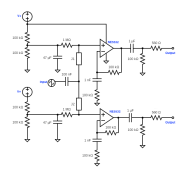
So, I started with a Klon like buffer circuit and essentially duplicated it twice. I was certain the unity gain design would actually give 2 unity output signals so I built in a gain of 1 in each half of the op amp. I’m not totally confident that I chose appropriate resistor and capacitor values where I modified the Klon circuit.
I attached the Klon schematic I used and my final schematic. I’d love some feedback on whether this is going to work. I’m looking forward to picking up my tools, breadbord and goodies when I’m back home for Christmas so I can try it out.
It’s good to be on here and I really look forward to any feedback.
Thanks so much!
I’m new to the forum and have drawn up a simple circuit today I’m hoping I can get a critique or three. But I thought I’d introduce myself first as the new guy.
I had a few analog circuit courses in college 30 years ago but never used it in my professional career so most of that knowledge was lost with time. Several years ago I attended a 2 day amp building class given by Bruce Egnater and it sparked my interest in tube guitar amp design. I’ve been a full-time RVer for a few years now so I don’t have the tools and equipment with me to work on anything anymore but want to get back into circuit design as it is great mental exercise now that I’m retired and slowly loosing brain cells! I recently started studying guitar effects hoping to build a few stomp boxes which is more feasible for me than working on big amps; given my space limitation.
I’ve started out pretty simple with a circuit I’m eventually going to use. I will have a need for a simple signal splitter that I can send one guitar signal to my amp and a second to my USB audio interface. The interface has a hi-z instrument input and I’m hoping to be able to record a raw guitar track, while also playing through a small amp, without the need to purchase or build a DI box. The recorded track will ultimately be used to reamp as part of my effect circuit breadboard tweaking.
So, I started with a Klon like buffer circuit and essentially duplicated it twice. I was certain the unity gain design would actually give 2 unity output signals so I built in a gain of 1 in each half of the op amp. I’m not totally confident that I chose appropriate resistor and capacitor values where I modified the Klon circuit.
I attached the Klon schematic I used and my final schematic. I’d love some feedback on whether this is going to work. I’m looking forward to picking up my tools, breadbord and goodies when I’m back home for Christmas so I can try it out.
It’s good to be on here and I really look forward to any feedback.
Thanks so much!

") - and the actual impedance remains defined by your external resistor value. BUT it's not a good choice for a passive guitar / bass pickup source. With a high Z source current noise becomes more important than voltage noise. A look at the respective figures for the opamps should tell the story.
- and the actual impedance remains defined by your external resistor value. BUT it's not a good choice for a passive guitar / bass pickup source. With a high Z source current noise becomes more important than voltage noise. A look at the respective figures for the opamps should tell the story.


![Soldering Iron Kit, 120W LED Digital Advanced Solder Iron Soldering Gun kit, 110V Welding Tools, Smart Temperature Control [356℉-932℉], Extra 5pcs Tips, Auto Sleep, Temp Calibration, Orange](https://m.media-amazon.com/images/I/51sFKu9SdeL._SL500_.jpg)


