chunger
Well-known member
Hi,
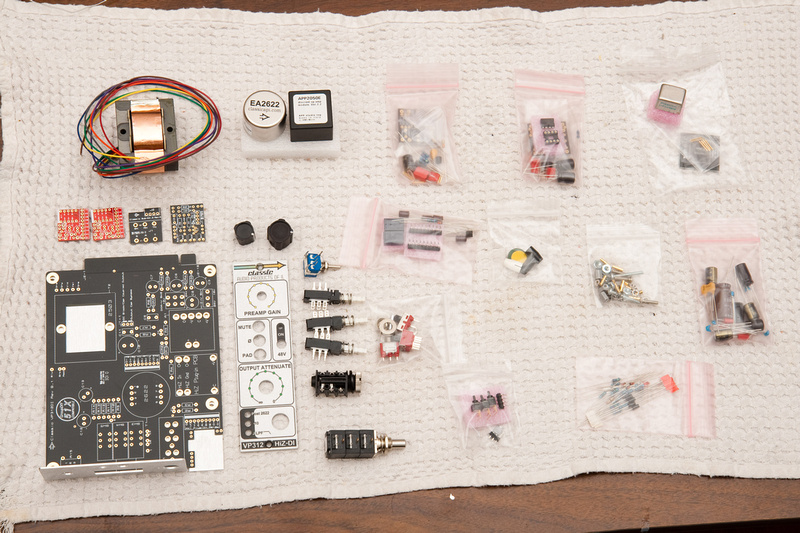
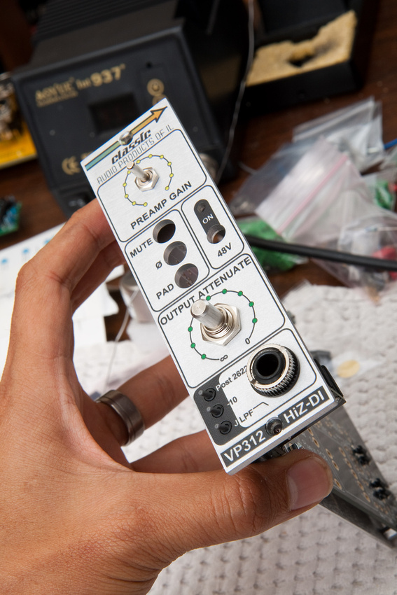
Newbie here. I've been lurking around for a while, and recently decided to jump on the GroupDIY 51x bandwagon and give DIY a try. In the search for beginner-friendly projects, I came across Jeff's API type preamp.
http://classicapi.com/catalog/product_info.php?cPath=22_47_55_56_58&products_id=175
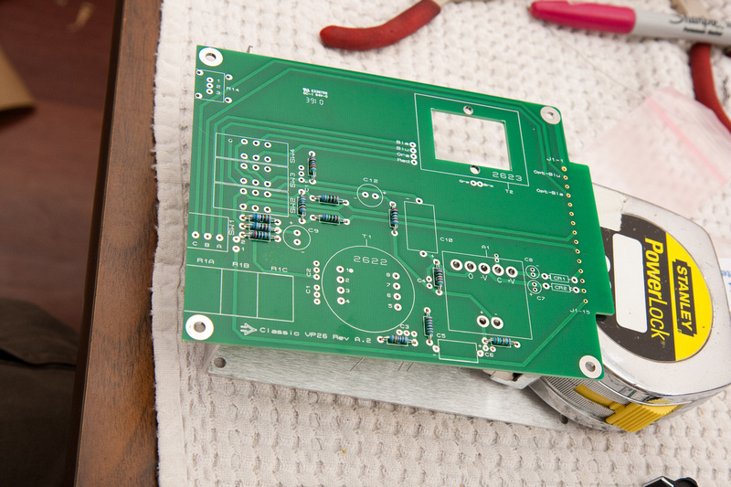
The step-by-step documentation for this project is so good, that I cannot add very much to what's already provided. Maybe a clearer picture here or there, but otherwise, completely redundant. This is more to get myself warmed up to DIY projects in general and to figuring out my documentation workflow. Plus, I'm waiting for parts to come in for the rack and the PSU, so I was getting a bit restless and wanted to keep moving forward.
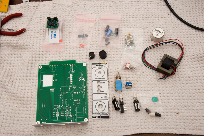
I don't know if it was foolish or not, but the first thing I tried was the gar 2520 op amp kit. . . uh. . . because the bag was smaller ???
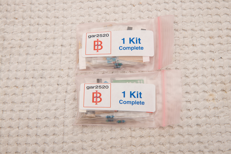
I bought a spare because I read this is a difficult build, and I figured a spare would be wise to have on hand given the low cost of the unit.
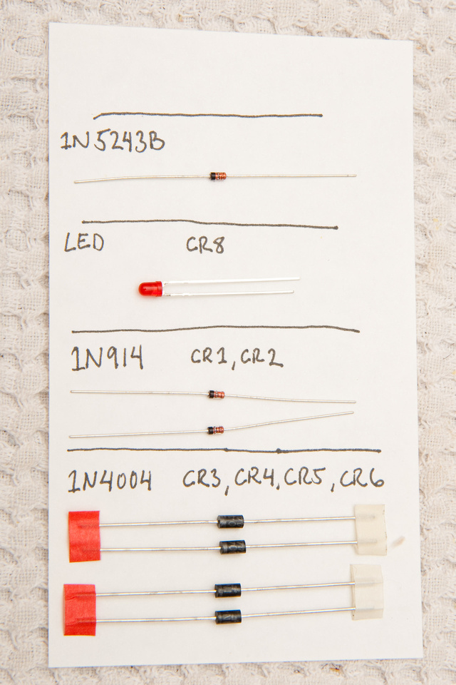
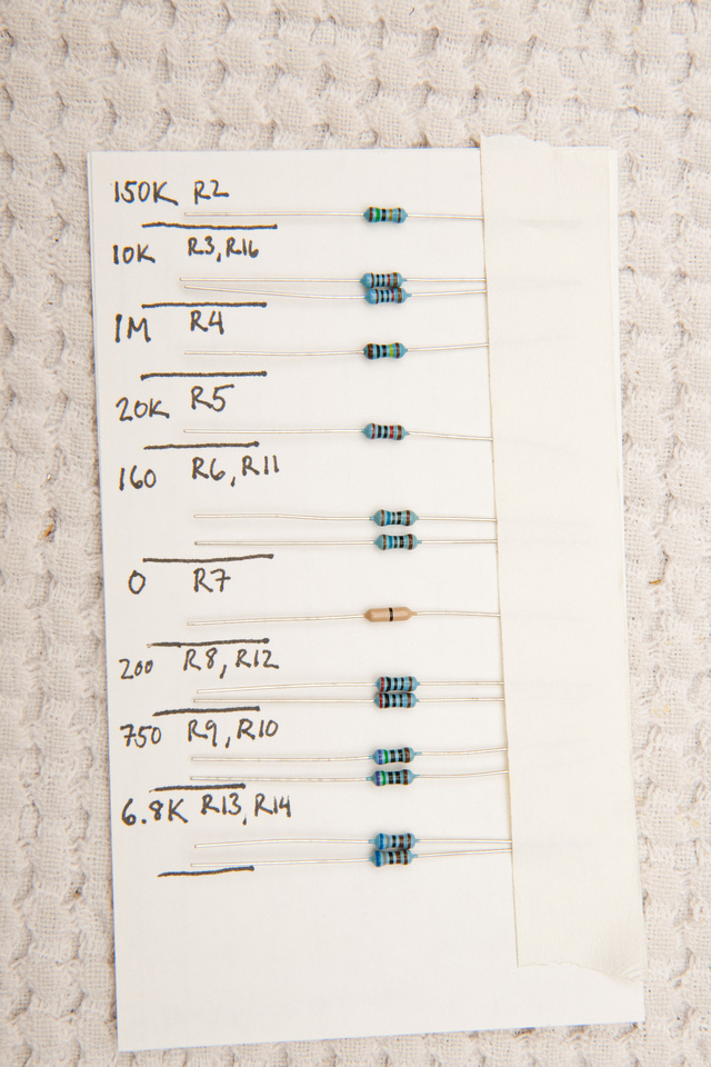
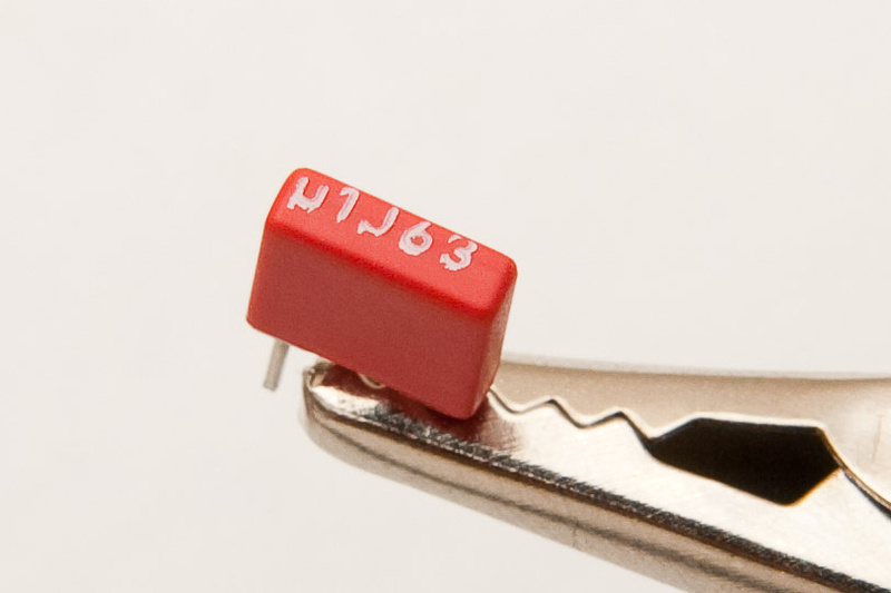
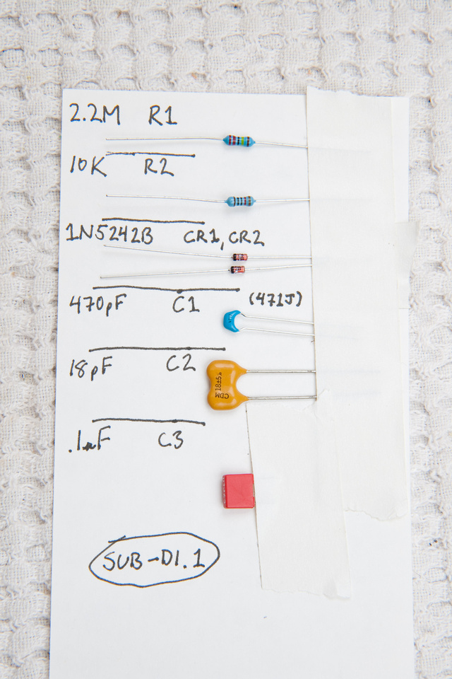
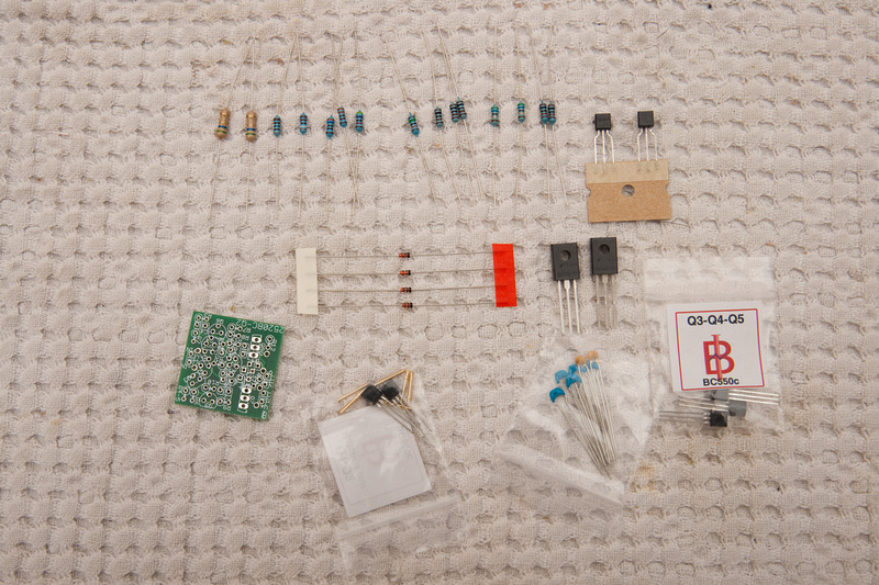
While not readily available online, the documentation that comes with this kit is ridiculously good. I have no idea what I'm doing, and probably would have been able to put this together based on the provided images alone, but I opened up a chart to identify resistor values, and pretty much that's all I needed to get through this op amp build.
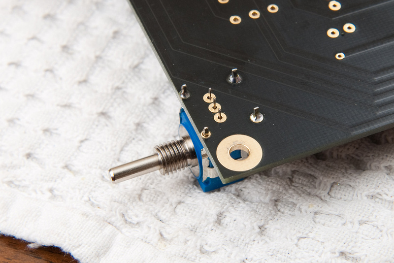
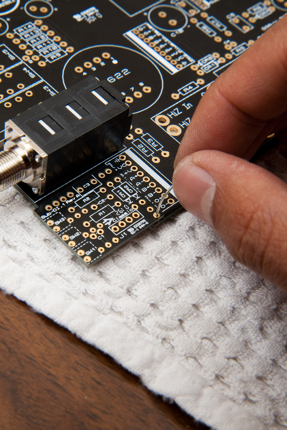
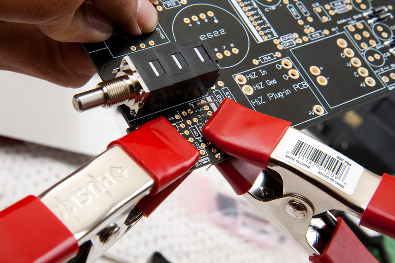
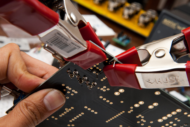
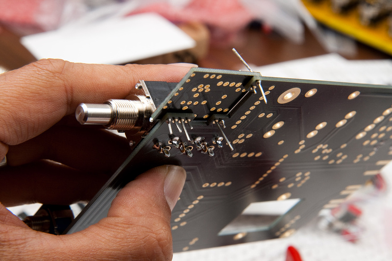
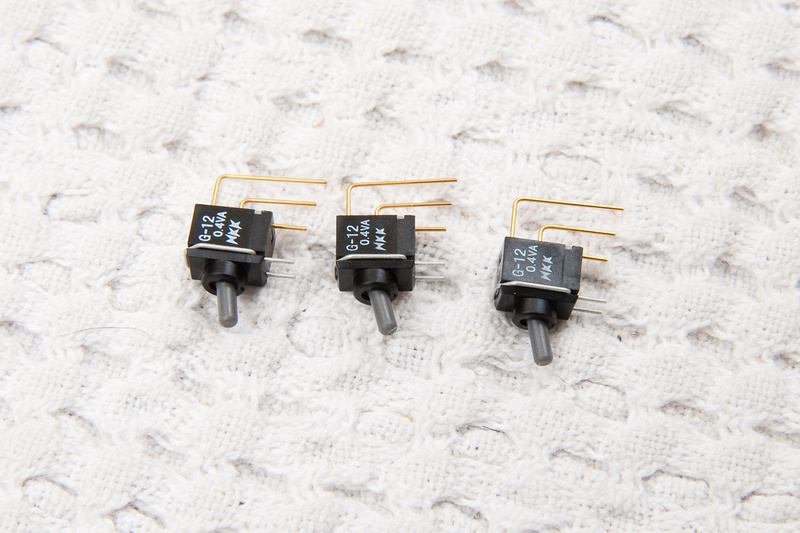
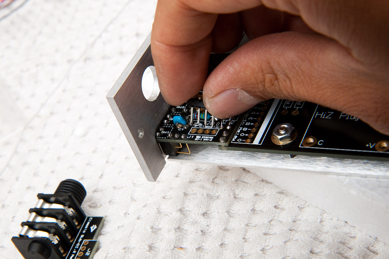
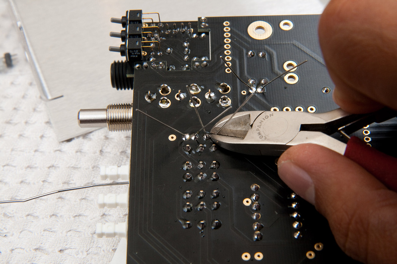
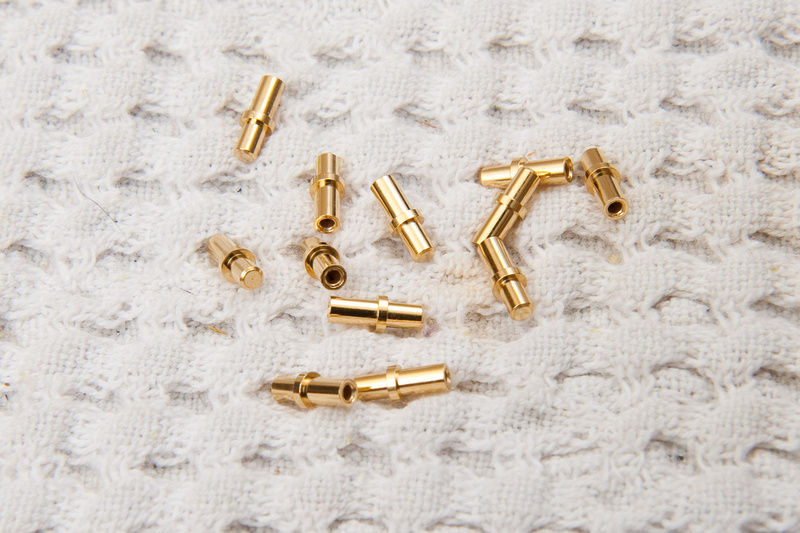
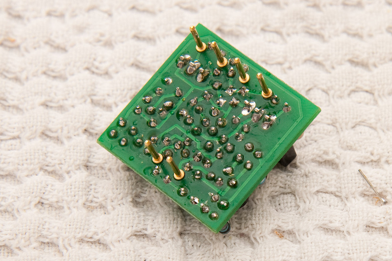
The only real difficulty I had was getting the pins to line up straight.
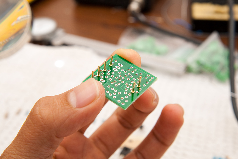
I tried flipping it over and putting it on a flat surface. . . that didn't look to workable.
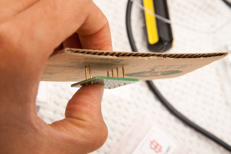
Then, I tried soldering a couple of pins on and then flipping it upside down and re-melting the solder to see if it wound naturally even out in the slots. . . and that didn't work too good either.
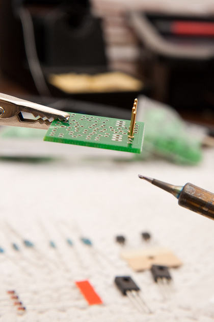
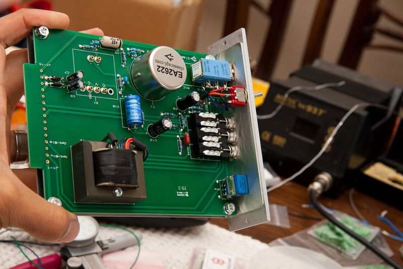
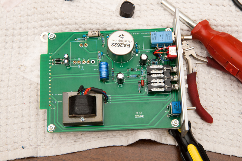
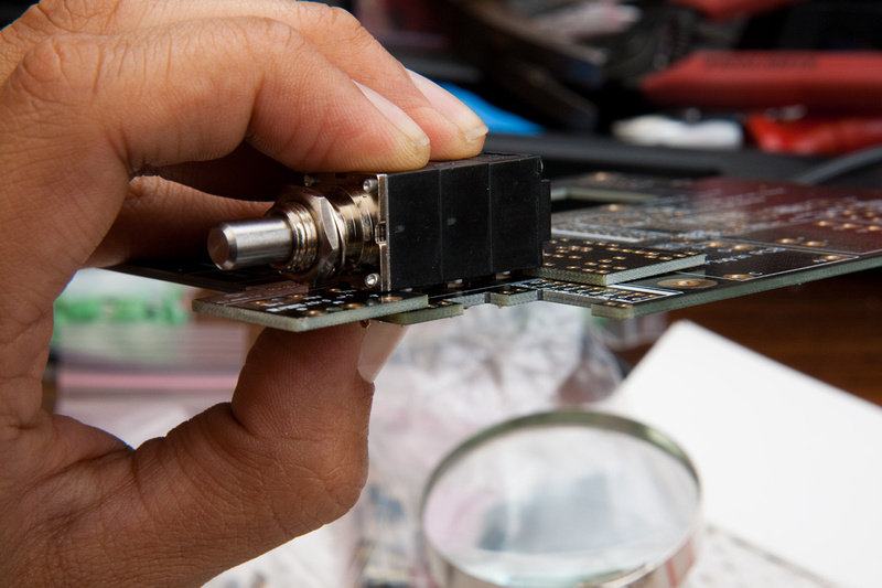
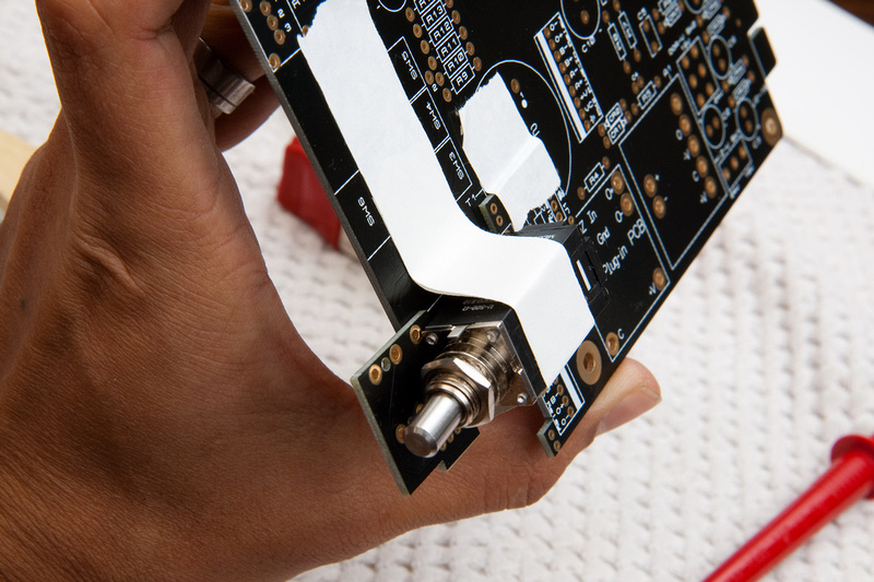
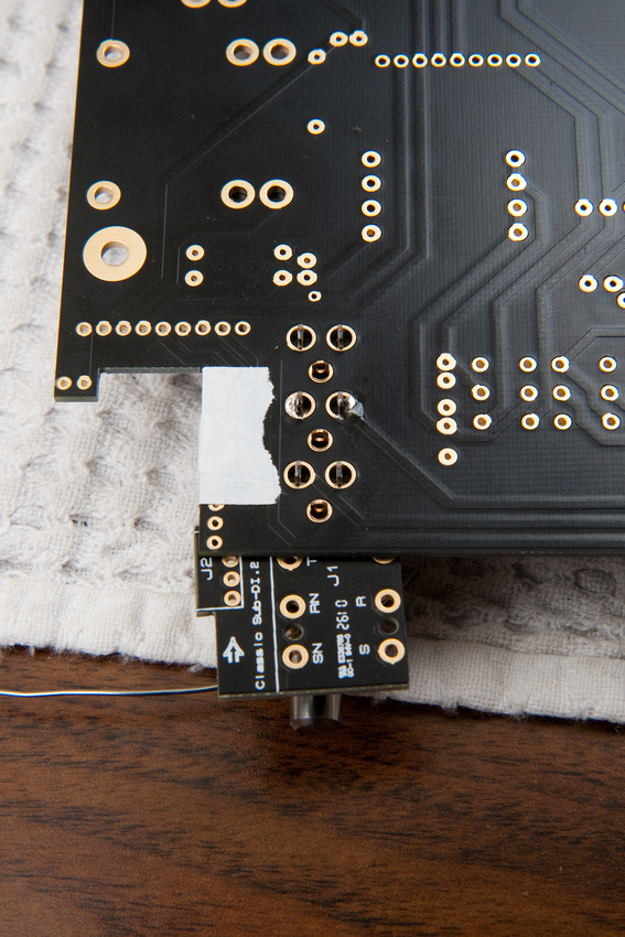
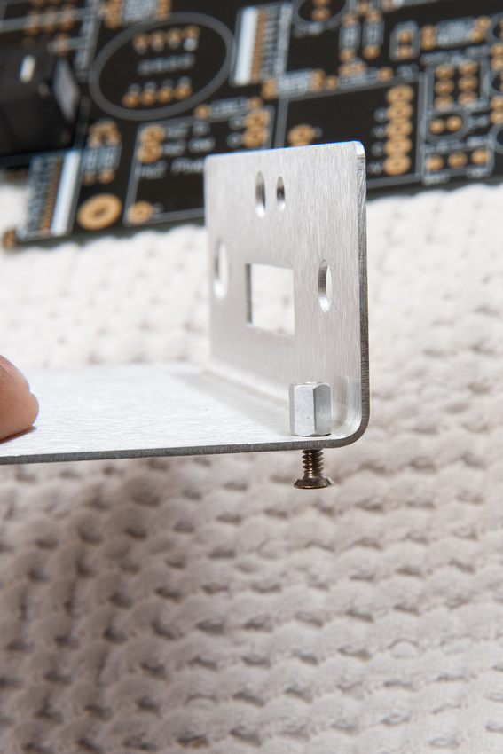
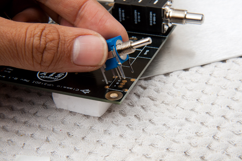
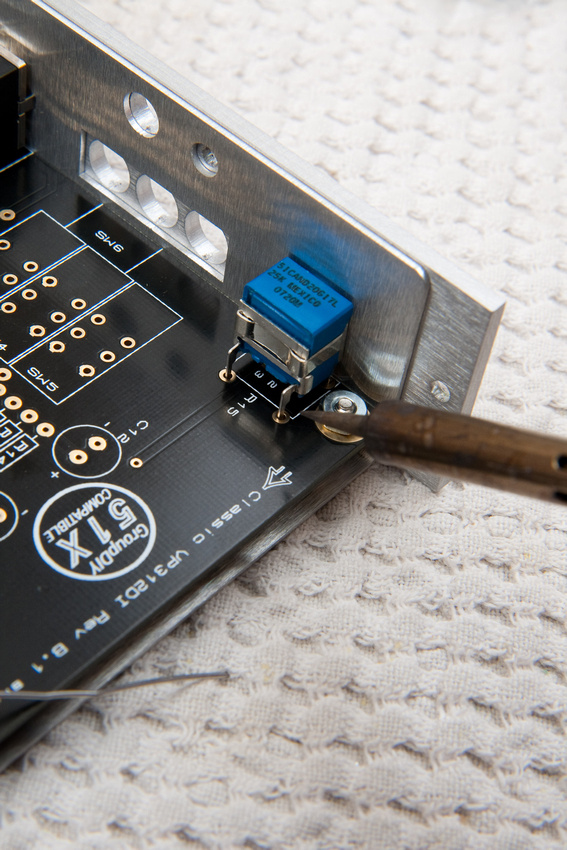
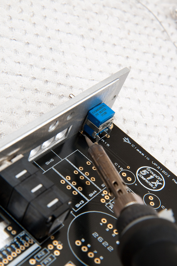
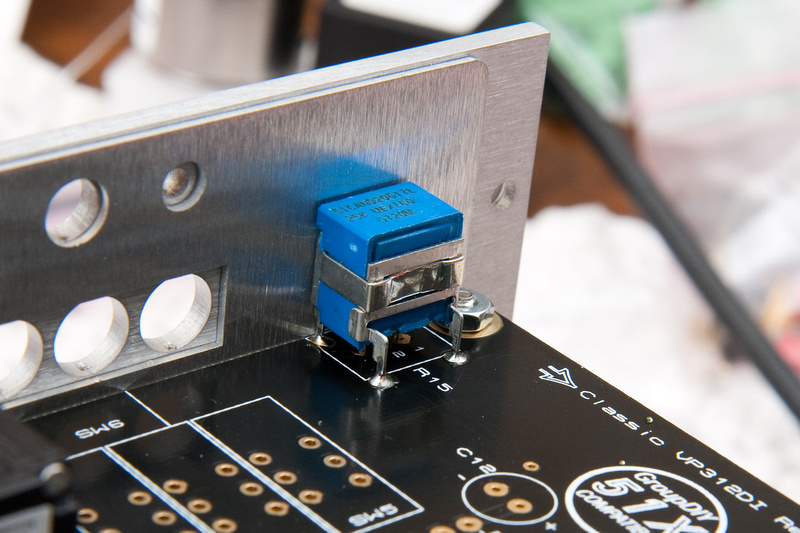
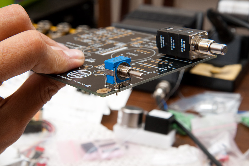
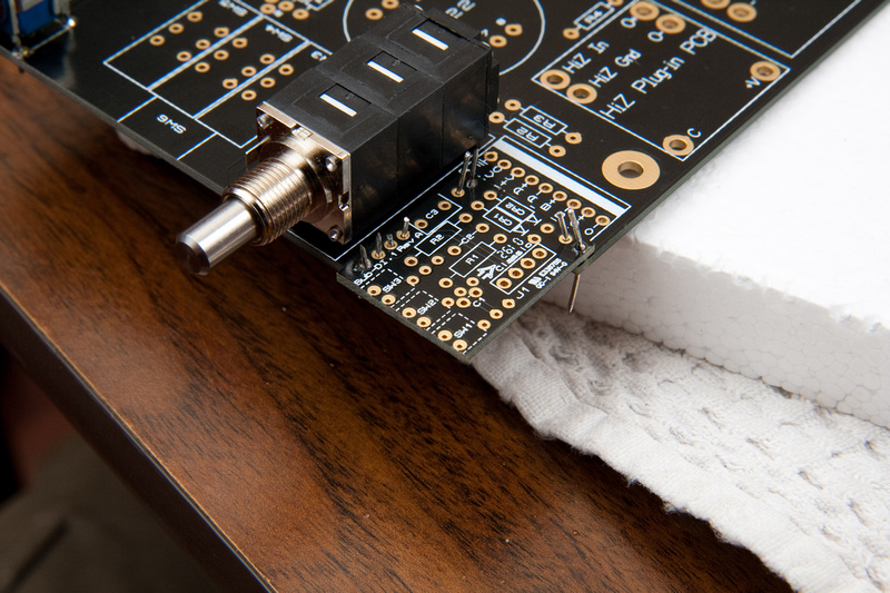
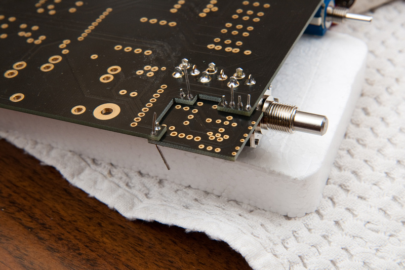
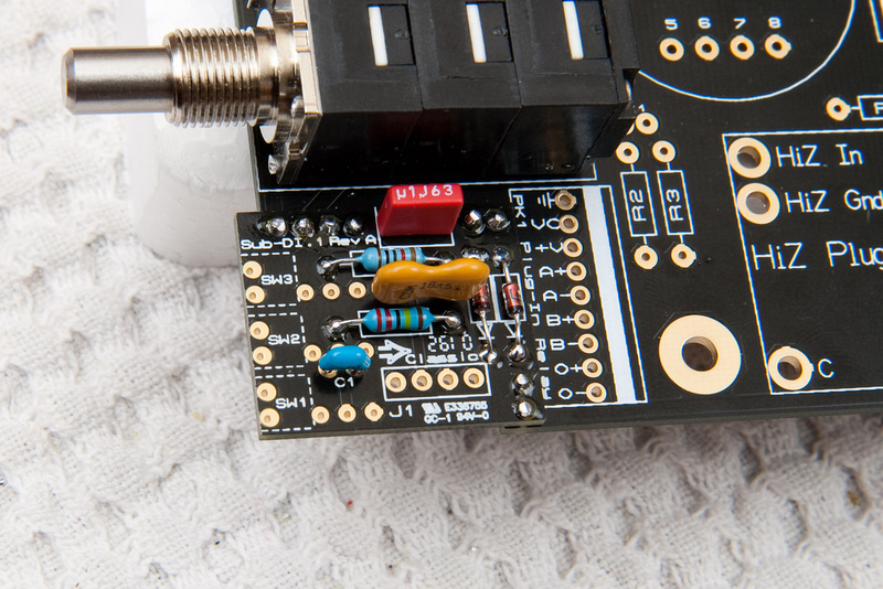
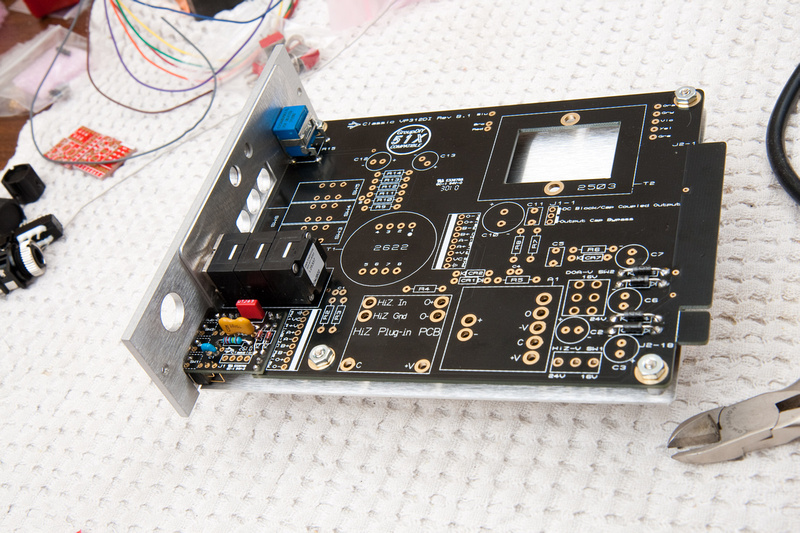
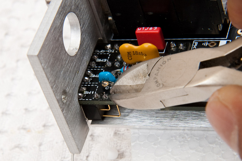
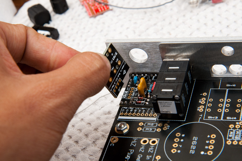
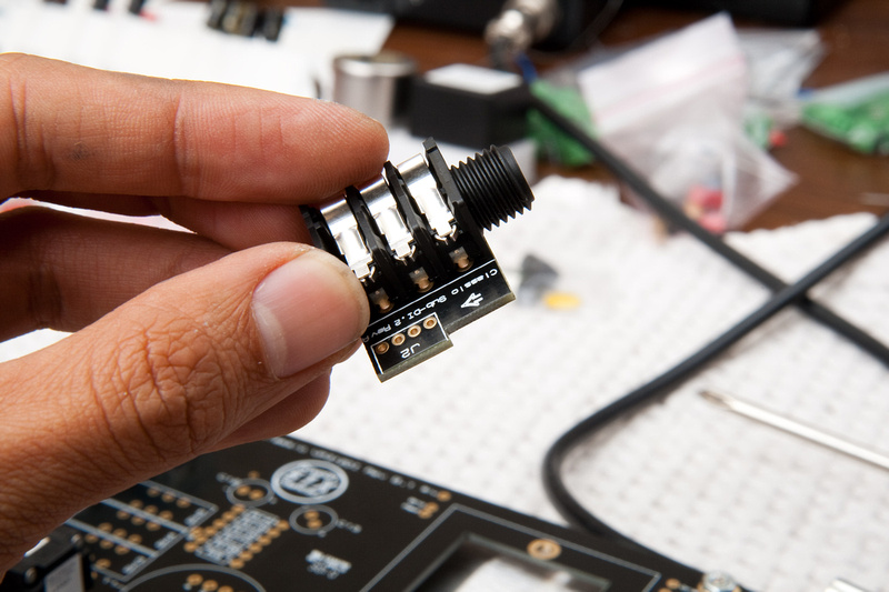
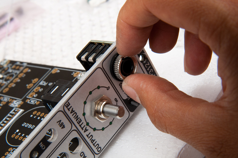
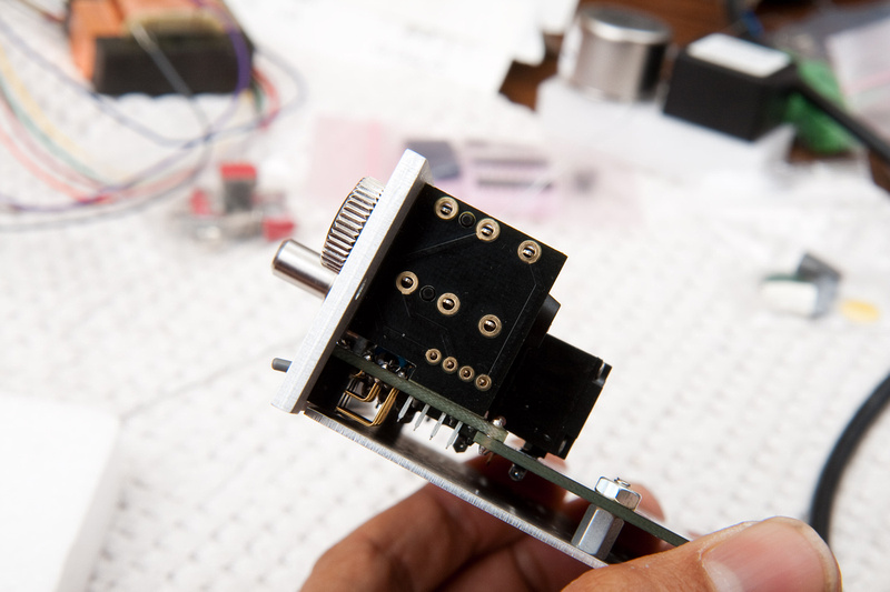
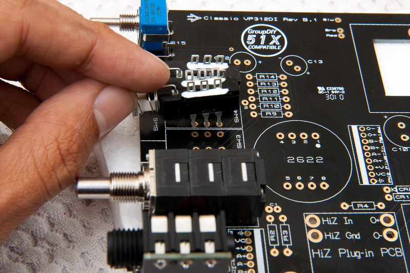
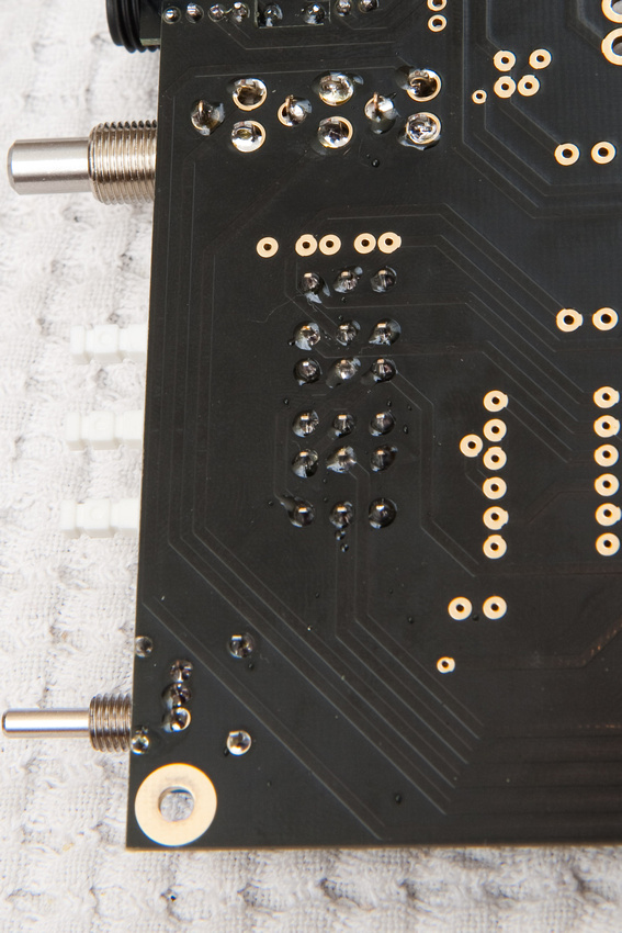
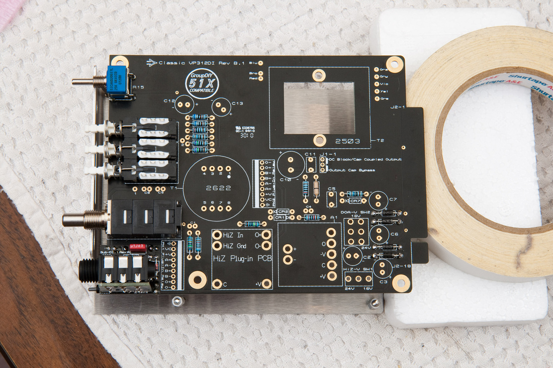
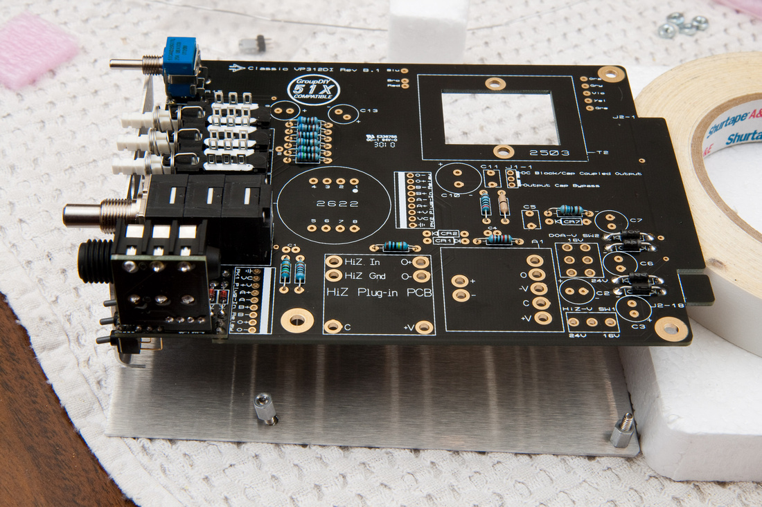
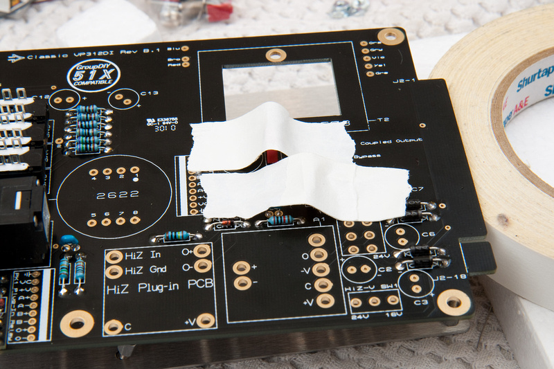
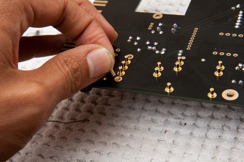
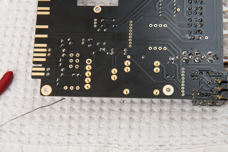
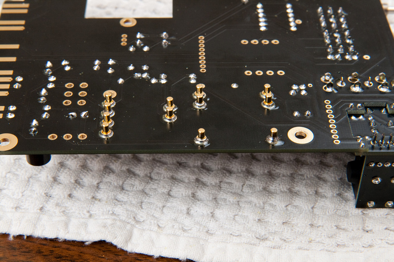
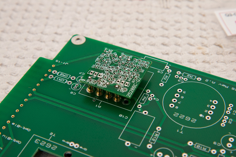
So, finally, I just pulled out the VP26 PCB and the inserts for the op amp and that gave me a much better chance of aligning the pins reasonably straight.
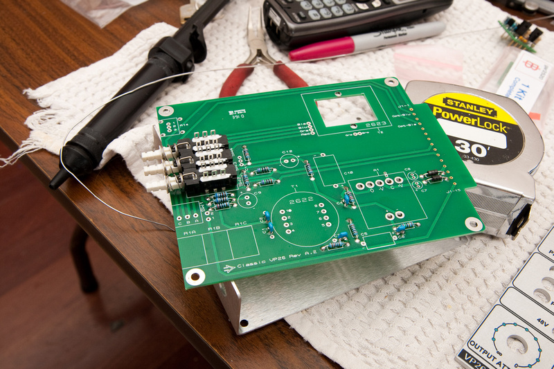
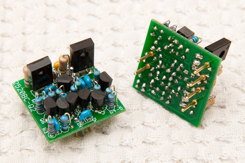
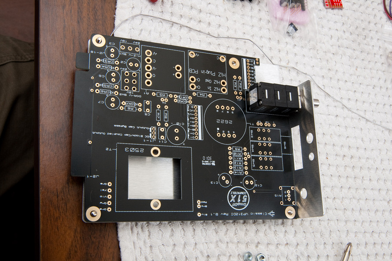
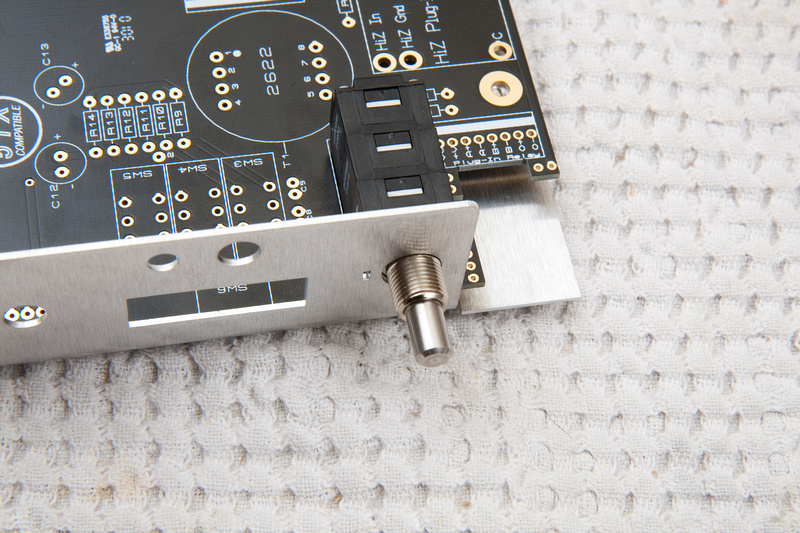
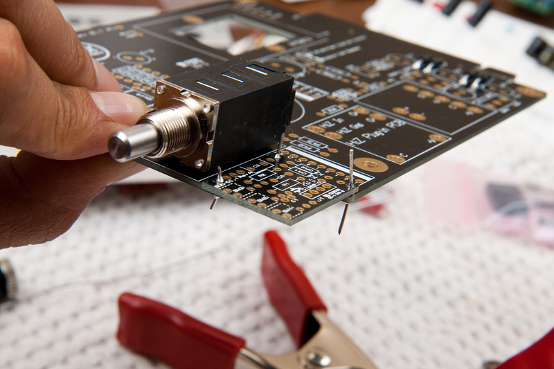
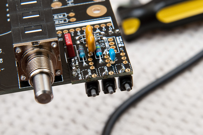
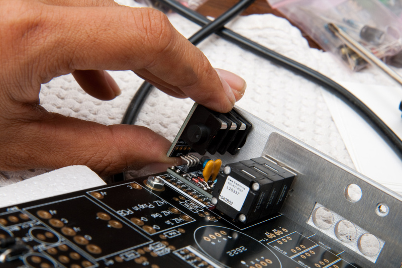
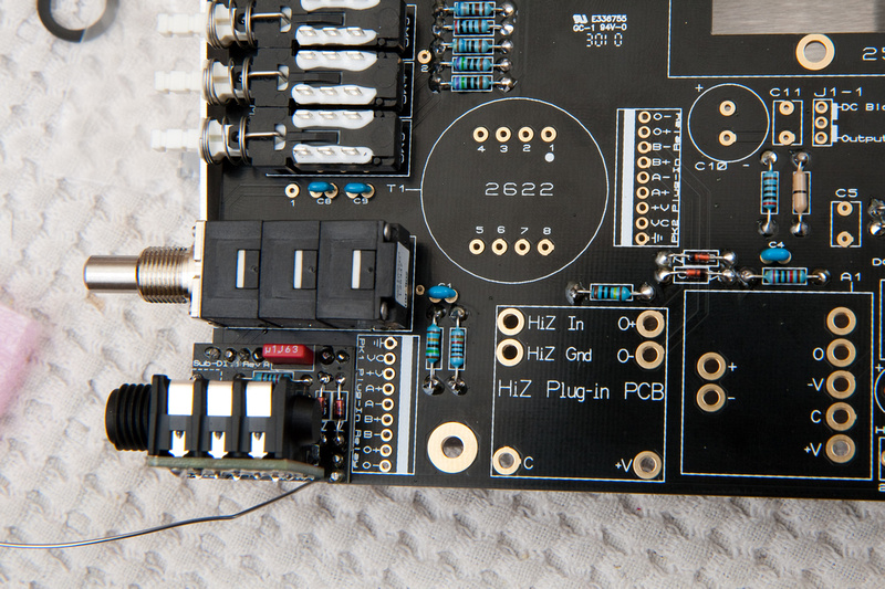
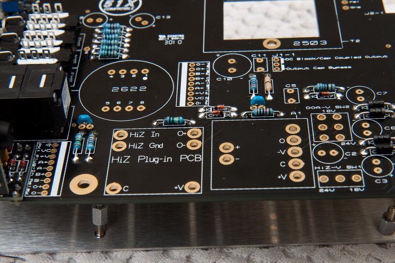
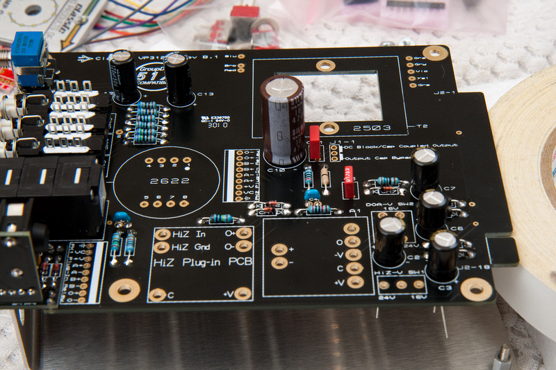
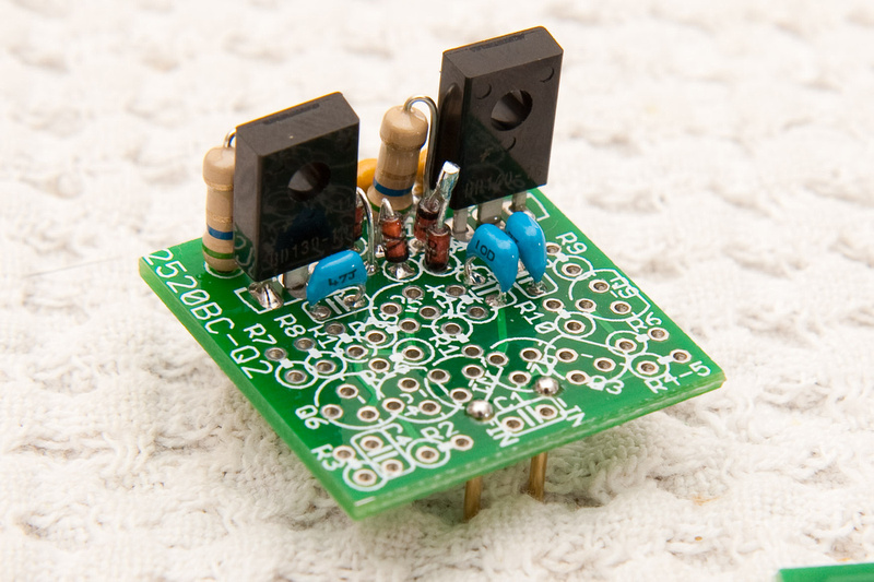
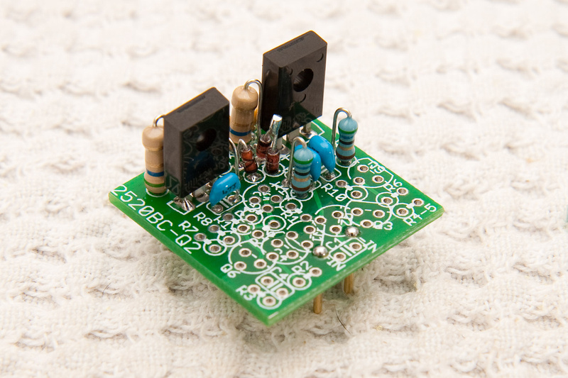
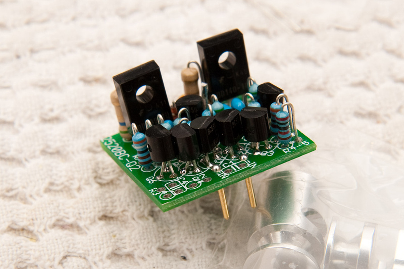
The rest is pretty much paint by numbers. As mentioned before, documentation photos, explanations, and diagrams leave nothing to the imagination. As long as I was paying attention to details, and my soldering was decent, I felt fairly confident the whole way through.
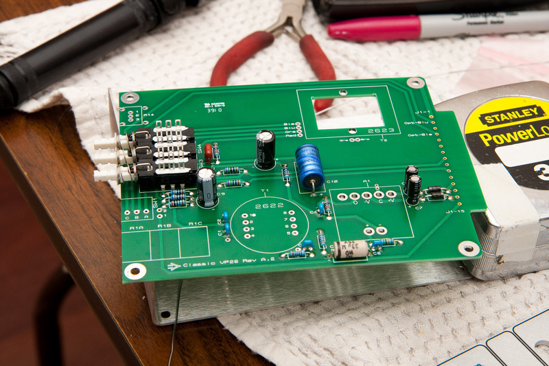
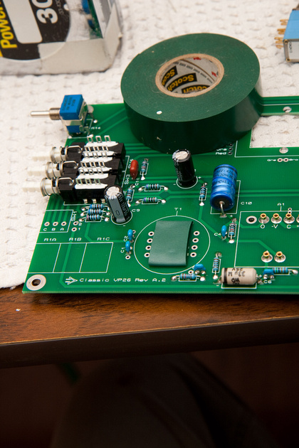
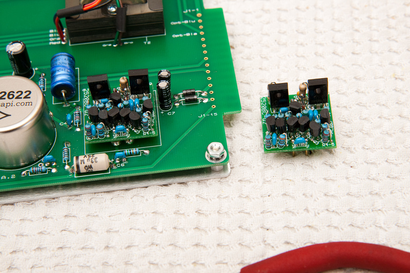
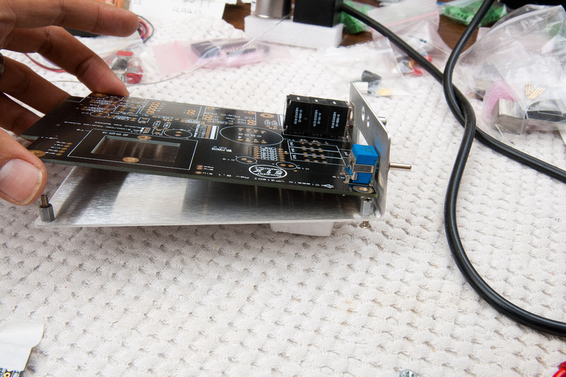
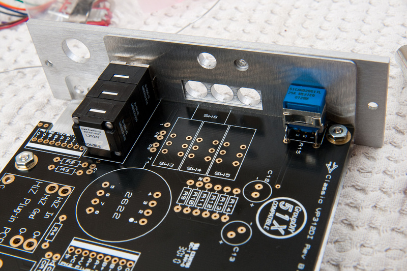
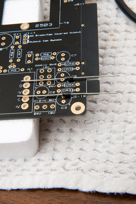
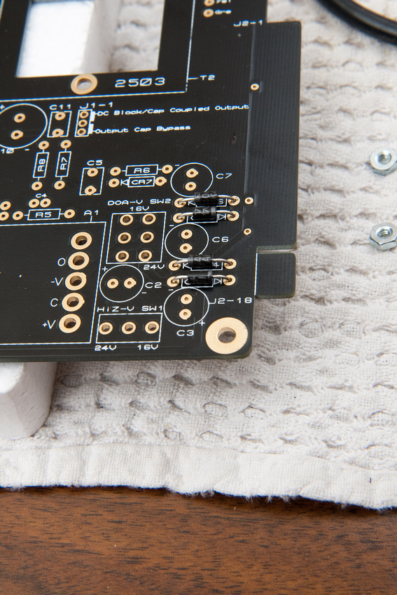
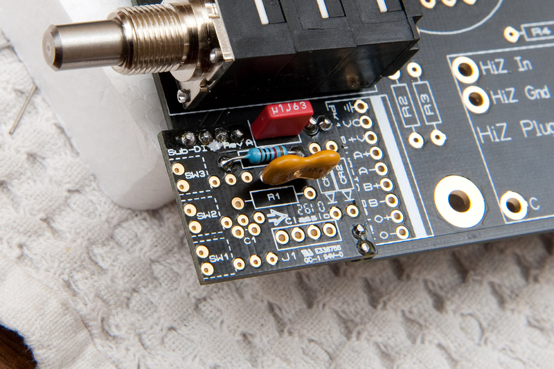
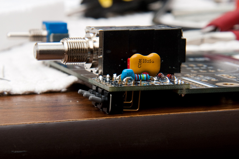
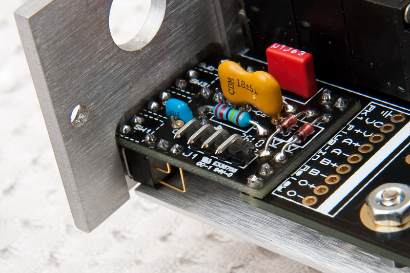
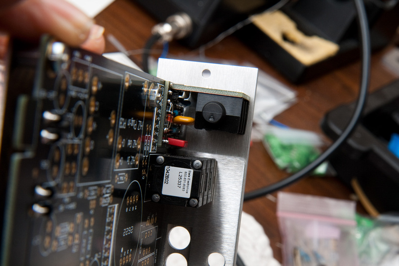
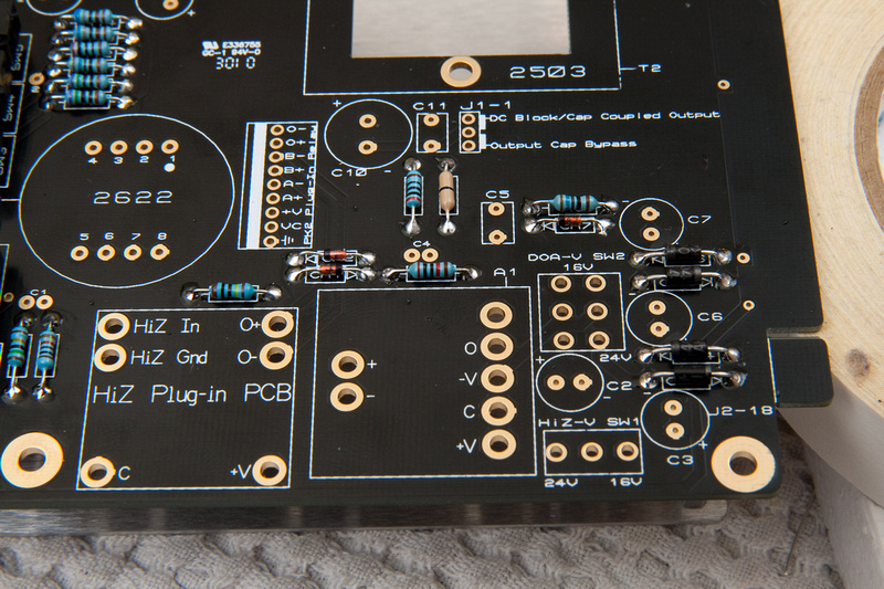
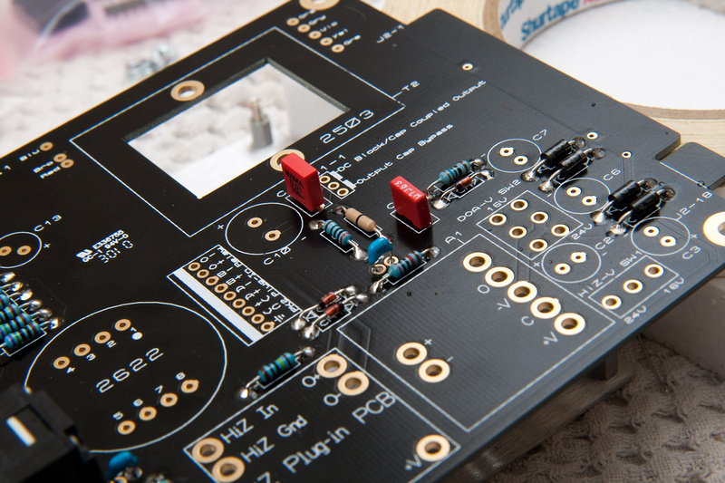
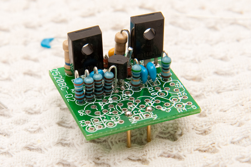
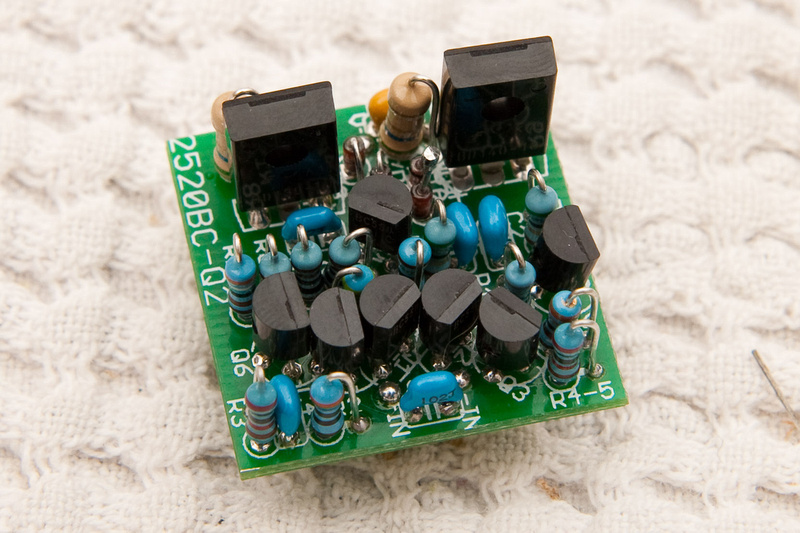
IMPORTANT NOTE: The 2 large transistors in these photos are REVERSED. . . BD139 should be on the right side and BD140 should be on the left side. The op amp if built in the manner pictured will be bricked.
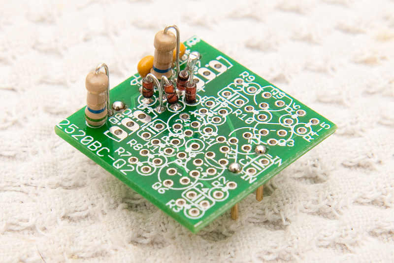
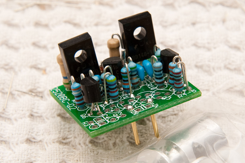
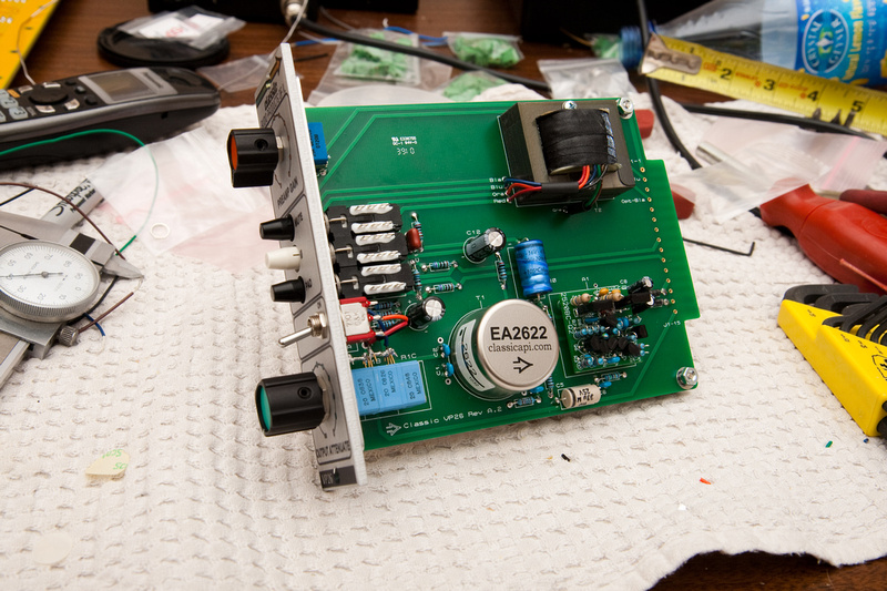
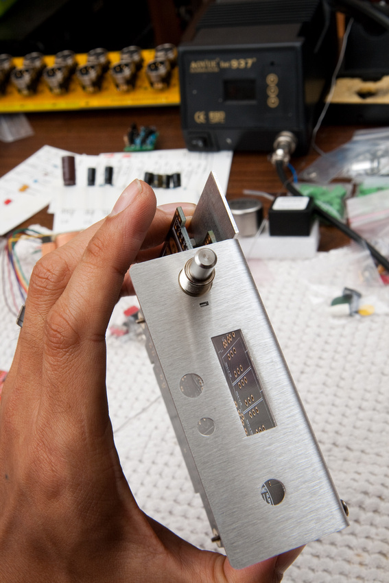
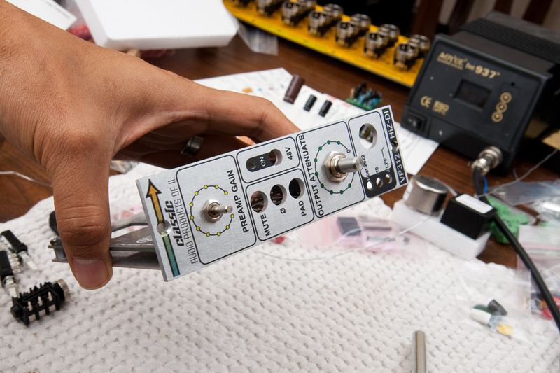
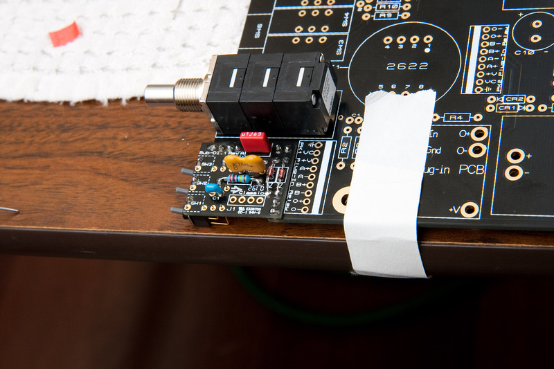
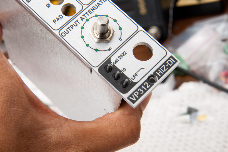
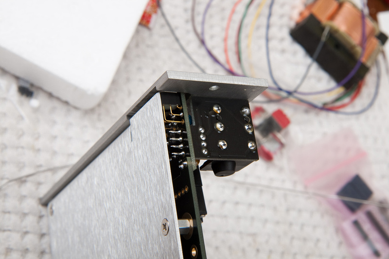
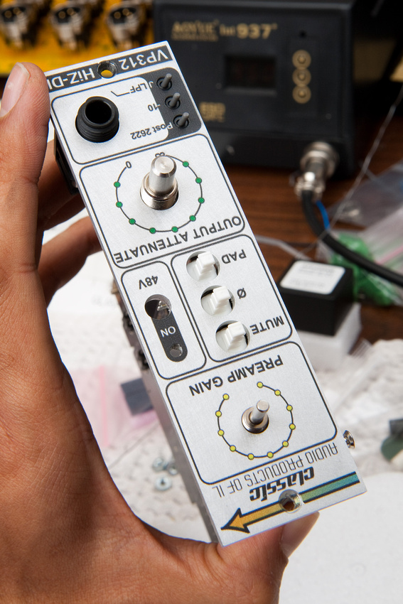
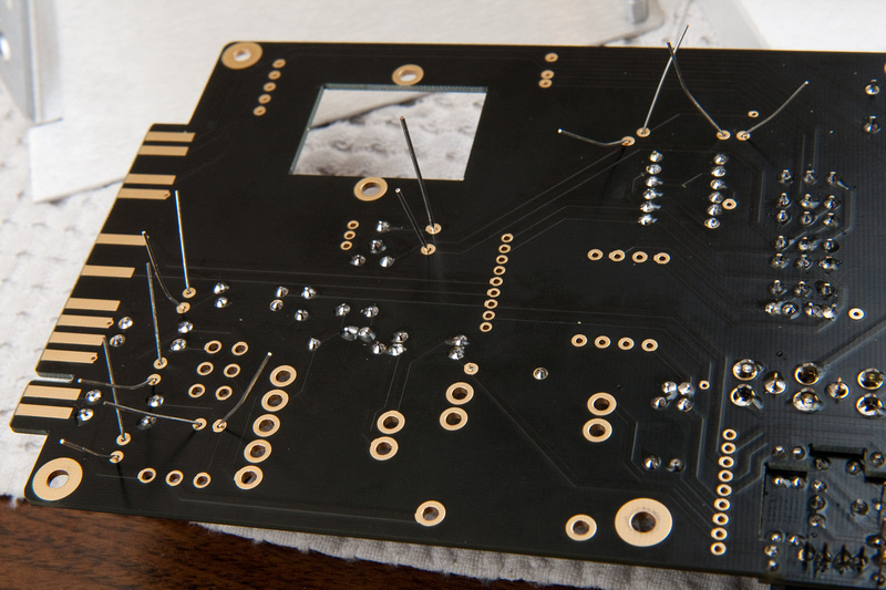
And. . . voila!
Does it work? I dunno. . . guess I'll find out.
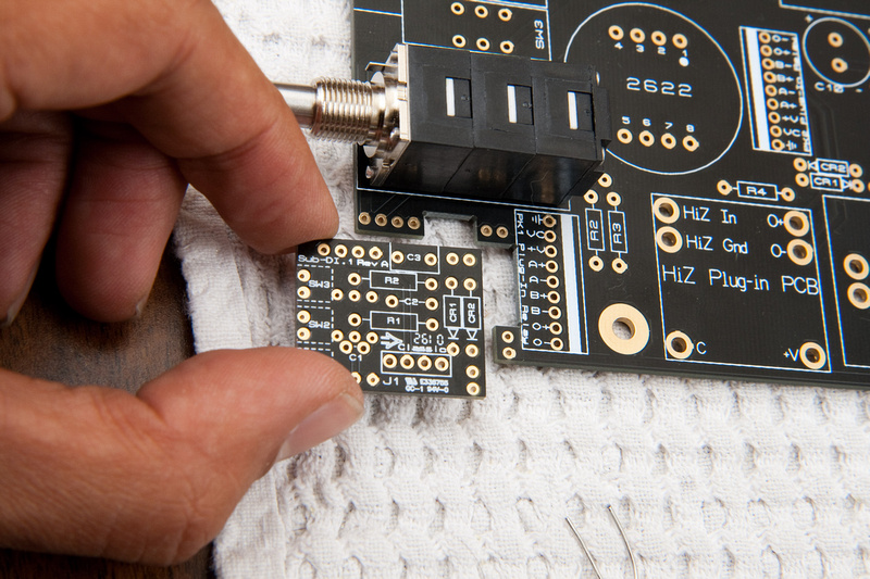
Next up. . . .
For this kind of work, I think it may be prudent for me to get a macro lens at some point. A lot of cropping going on. For web, you'd never know. Macro would be nice though , but I do what I can with what I have. Focus is also a bit touchy. I should see if I can buy myself another f stop or 2 somehow.
Newbie here. I've been lurking around for a while, and recently decided to jump on the GroupDIY 51x bandwagon and give DIY a try. In the search for beginner-friendly projects, I came across Jeff's API type preamp.
http://classicapi.com/catalog/product_info.php?cPath=22_47_55_56_58&products_id=175
The step-by-step documentation for this project is so good, that I cannot add very much to what's already provided. Maybe a clearer picture here or there, but otherwise, completely redundant. This is more to get myself warmed up to DIY projects in general and to figuring out my documentation workflow. Plus, I'm waiting for parts to come in for the rack and the PSU, so I was getting a bit restless and wanted to keep moving forward.
I don't know if it was foolish or not, but the first thing I tried was the gar 2520 op amp kit. . . uh. . . because the bag was smaller ???
I bought a spare because I read this is a difficult build, and I figured a spare would be wise to have on hand given the low cost of the unit.
While not readily available online, the documentation that comes with this kit is ridiculously good. I have no idea what I'm doing, and probably would have been able to put this together based on the provided images alone, but I opened up a chart to identify resistor values, and pretty much that's all I needed to get through this op amp build.
The only real difficulty I had was getting the pins to line up straight.
I tried flipping it over and putting it on a flat surface. . . that didn't look to workable.
Then, I tried soldering a couple of pins on and then flipping it upside down and re-melting the solder to see if it wound naturally even out in the slots. . . and that didn't work too good either.
So, finally, I just pulled out the VP26 PCB and the inserts for the op amp and that gave me a much better chance of aligning the pins reasonably straight.
The rest is pretty much paint by numbers. As mentioned before, documentation photos, explanations, and diagrams leave nothing to the imagination. As long as I was paying attention to details, and my soldering was decent, I felt fairly confident the whole way through.
IMPORTANT NOTE: The 2 large transistors in these photos are REVERSED. . . BD139 should be on the right side and BD140 should be on the left side. The op amp if built in the manner pictured will be bricked.
And. . . voila!
Does it work? I dunno. . . guess I'll find out.
Next up. . . .
For this kind of work, I think it may be prudent for me to get a macro lens at some point. A lot of cropping going on. For web, you'd never know. Macro would be nice though , but I do what I can with what I have. Focus is also a bit touchy. I should see if I can buy myself another f stop or 2 somehow.
 . But, same folding table ;D.