Not another led meter question...

GroupDIY Audio Forum

Help Support GroupDIY Audio Forum:

This site may earn a commission from merchant affiliate links, including eBay, Amazon, and others.

3nity

Well-known member
Joined
Dec 30, 2005
Messages
3,642
Location
MTL, CANADA
just wanna see if i'm doing things right here just before pull the etching stuff..
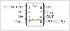
I'm using a TL072/IC2 and LM3914/IC1
I wanted something like the Pico led meter but simpler and at the same time variable like the Silvas variable scale meter as seen here:
http://www.groupdiy.com/index.php?topic=30057.0

so heres my schem....
normal_LED.JPG


OR bigger:
http://www.twin-x.com/groupdiy/albums/userpics/LED.JPG
 
Couple comments...

LM 3914 is linear scale...not log. Is that what you want?

Also, i'd consider a full wave precision rectifier on the input. I use a TL 072. Not very complicated.
Audio peaks are pretty asymmetric.

Les
L M Watts Technology
 
Alright thanks.
You're right Sorry ITs TL071 on IC2.

And this is a linear scale I'm using TL071 how you find it? Les?
 
how you find it? Les?

Looks ok I think. if you want linear. It will only respond to negative peaks at the op amp input.

Let me get my data sheets. I'll double check it. I just built up a whole bunch of these for some preamps.

Give me an hour or so...

Les
 
Ok, checked it.

I think I see a problem with your R5.

Usually a divider is set up with 2 resistors to independently control the 3914 sensitivity and LED current.
You can use it with a single resistor, but it needs to be hooked up as per page seven of the data sheet.
It needs to go from pins 6 and 7 to ground, with pin 8 also grounded. This will make the top led light at 1.25 volts, and the resistor value will program the led current.

The only other thing I see is that with most switches the contacts are break before make (non shorting).
This would glitch the display while the switch is changed, since the op amp feedback resistor will be unhooked for a short time, giving it a very high gain.

Again, this circuit will respond to negative voltages only at the op amp input.

So just check page seven of this:
http://www.national.com/ds/LM/LM3914.pdf

Les
L M Watts Technology
 
Hey Less gracias!
Thanks for that missing resistor.
Now what you mean by:
Again, this circuit will respond to negative voltages only at the op amp input.

I'm using this on a GSSL.
Thanks.
 
The 3914 indicates positive voltages only. Your op amp is inverting, so that will make the system respond to negative voltages only.

I think this is correct for the GSSL. I think you have it right. I took a quick glance at the schematic and the sidechain control voltage looks to be negative.

So...looks ok. You might want to check with the GSSL people in the "lab". I only looked at it briefly, because audio compressors make me sad. :( :D

Les
L M Watts Technology
 
Hello Jorge !

When i was prototyping my variable-scale meter board, i found quite hard to find the correct resistor values for the scales i wanted...i would replace R1, R2, and R3 with multiturn trimmers as on my board...with the added benefit that in the future you can calibrate your meter with a different GR range if you want or need to. I remember calibrating the scales watching and measuring the actual gain reduction on the GSSL, the accuracy is great specially on the 5dB scale. Never needed to calibrate my meter for, say, 2dB, but it is possible.

 
Hey everyone. Hoping you might help a noob troubleshoot this thing. I have a working GSSL. Wired up this meter on a stripboard, but i can't get the meter to do anything. I checked for +/-15v everywhere and that seems okay. The pins of the 3914 that are connected to the LED's are all sitting at like 14v (regardless of signal) and no LED's are lighting. Not sure what else to try... Anyone have any ideas?
 
We can try, although it's not easy to diagnose over the internet.

I'd first confirm signal at the 3914 input pin. The double check LED polarity.

Could you post a schematic?

Les
L M Watts Technology
 
Hi Les,

I definitely understand. I really appreciate the help!

I'm using this schematic from this thread.

I have checked my wiring a few times (and LED polarity, which seems to be correct). I've also made sure there are no shorts on my stripboard. At work now, but tonight i will go over my wiring again and ensure that i am getting signal to the 3914, thanks for the advice!
 
Ok. we'll see what you find.

I took a look at the circuit. I calculate Top LED lights at 2.05v with R1 set to max.

Assuming R1 is a pot Iled is about 20 ma with R1 set to max. With R1 set to min (0)
the Iled formula 12.5v/R1 term blows up, and I'm not liking that...

Did anyone else actually try this?

Les
 
Assuming R1 is a pot Iled is about 20 ma with R1 set to max. With R1 set to min (0)
the Iled formula 12.5v/R1 term blows up, and I'm not liking that...

I actually used fixed resistors for R1. I can't remember the exact values offhand, but i think it was within like 4% of 1.133k. So i don't think i'd have an issue with accidentally setting R1 to 0 or anything...
 

Latest posts

Back
Top