


- Joined
- Jul 15, 2009
- Messages
- 2,306
aaquilato said:I'm going to end this post by saying, don't bother with this DIY kit.
I've had more headaches with all the misinformation and incomplete packaging than any other DIY kit I've worked on.
It's just not worth it.
Thank you everyone for your help and support.
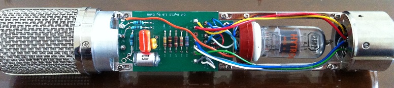
Have you been using the PCB or the point to point version,
Just curious,
Let me know if you have a chance,
Best,
dAN,
")


![Electronics Soldering Iron Kit, [Upgraded] Soldering Iron 110V 90W LCD Digital Portable Soldering Kit 180-480℃(356-896℉), Welding Tool with ON/OFF Switch, Auto-sleep, Thermostatic Design](https://m.media-amazon.com/images/I/41gRDnlyfJS._SL500_.jpg)


