Official C12 Clone - Build and Support Thread

GroupDIY Audio Forum

Help Support GroupDIY Audio Forum:

This site may earn a commission from merchant affiliate links, including eBay, Amazon, and others.
Neutrino said:
Hi all,

quick question here: Is it possible to use a cheap Chinese k67-type capsule in a 251E build for testing purposes before attaching an expensive CT12 capsule? I don't see any reason why not.

Cheers,
Waldemar

Yes absolutely. Or even 1 or 2 pcs of 75pf  capacitors can do the job.
 
Neutrino said:
Hi all,

quick question here: Is it possible to use a cheap Chinese k67-type capsule in a 251E build for testing purposes before attaching an expensive CT12 capsule? I don't see any reason why not.

Cheers,
Waldemar
Absolutely! I do it all the time.
 
Thank you for the quick replies!  ;)

I got the PSU and the 251 finished now and I'm currently testing with a k67-type capsule and a JJ electronics 12AY7 tube.

Without any load across B+ and GND (no mic connected) the minimum voltage I can obtain with the trim pot is 192 Volts. This is expected to go down once the mic is connected, but it doesn't  :eek:. I watch the voltage rising and switch the PSU off when it reaches 150 Volts to avoid any damage. As I said I cannot reduce it any further as the trim pot is at the limit.

Any ideas what I could test? Can it be related to the tube that I'm using? I bought it new (and cheap) and it has not been "burned-in" before.

Cheers,
Waldemar
 
Neutrino said:
Without any load across B+ and GND (no mic connected) the minimum voltage I can obtain with the trim pot is 192 Volts. This is expected to go down once the mic is connected, but it doesn't

This is normal! The trimpot is in series with the B+ line, so: no load, no regulation!
If there is still no regulation with the microphone connected (and the tube in place) there is something wrong.
It seems that there is no current in this case.
 
RuudNL said:
This is normal! The trimpot is in series with the B+ line, so: no load, no regulation!
If there is still no regulation with the microphone connected (and the tube in place) there is something wrong.
It seems that there is no current in this case.

Oh,  I think my statement wasnt't clear. I CAN regulate the voltage with the trimpot. E.g. with the 180k resistor between B+ and GND I am able to regulate it precisely to 120 Volts.

But when I attach the microphone with that setting, the B+ voltage rises much higher and the available turns in the pot are not sufficient to regulate it down to 120 Volts again.
 
So with the suggested load resistor of 180 K you get 120 V?
This means a current of about 0.66 mA.
The trimpot is 100 K, so at maximum resitance you will get a voltage drop of 66 V over the trimpot alone.
I suppose in your situation the tube has a plate current of less than 0.66 mA.
This could be the result of a too high negative voltage on the grid of the tube.
Does adjusting R3 (bias) in the powersupply change the +B voltage?
Did you check the bias voltage also?
Also keep in mind that it takes some time for the tube to heat up.
At the moment you switch on the power supply, the cathode is still cold and is not emitting electrons, so initially no current is flowing.
It might take up to 30 seconds before the tube has reached a normal working temperature.
This will cause the supply voltage (under load) to drop after a certain amount of time.
 
Neutrino said:
Any ideas what I could test? Can it be related to the tube that I'm using? I bought it new (and cheap) and it has not been "burned-in" before.
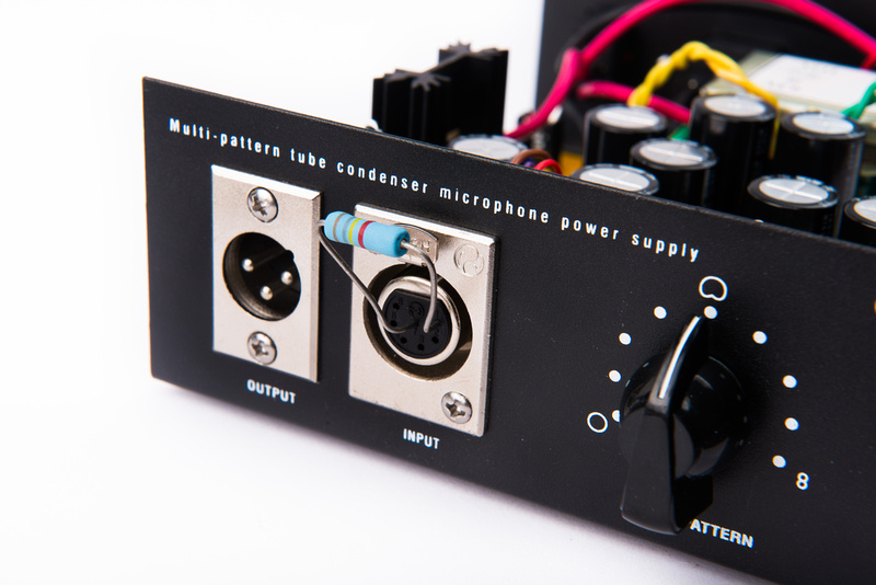
Use a test load across B+ and ground to set the initial voltage.  Chunger shows it somewhere in the past 100+ pages. :)  You just stick it right into the 7-pin XLR connector at the PSU, since that side has holes for the legs of the test resistor.  Use 180K,  1/2W.

EDIT: I found it.

p291080247-4.jpg
 
RuudNL said:
So with the suggested load resistor of 180 K you get 120 V?
This means a current of about 0.66 mA.
The trimpot is 100 K, so at maximum resitance you will get a voltage drop of 66 V over the trimpot alone.
I suppose in your situation the tube has a plate current of less than 0.66 mA.
This could be the result of a too high negative voltage on the grid of the tube.
Does adjusting R3 (bias) in the powersupply change the +B voltage?
Did you check the bias voltage also?
Also keep in mind that it takes some time for the tube to heat up.
At the moment you switch on the power supply, the cathode is still cold and is not emitting electrons, so initially no current is flowing.
It might take up to 30 seconds before the tube has reached a normal working temperature.
This will cause the supply voltage (under load) to drop after a certain amount of time.

Yes, with 180k load resistor, I get 120 V out of the PSU.
Mind that I'm building a ELAM 251E. So there is no bias voltage supply.
But I measured the voltages at cathode (0 V) and grid (few mV) which are probably too small  :eek:
The measurements are taken after at least 1 min heat up time.
 
Matador said:
Use a test load across B+ and ground to set the initial voltage.  Chunger shows it somewhere in the past 100+ pages. :)  You just stick it right into the 7-pin XLR connector at the PSU, since that side has holes for the legs of the test resistor.  Use 180K,  1/2W.

EDIT: I found it.

Thanks, Matador! Actually, with a load resistor of 180 k, I am able to trim the B+ voltage to 120 V. It looks like the problem is more with the mic itself ?
 
Oops, I missed that somehow.  For some reason the tube is not conducting current.

Is the heater correctly trimmed at 6.3V?  Can you see the heater lighting up in the tube?  Which side of the tube did you select?    If you are using the 'A' side (pins 1,2,3), then the heater voltage must be present across pins 4 and 9.  If you selected side 'B' (6,7,8), then the heater voltage will be present across pins 5 and 9. 

I would measure this right at the tube socket pins.  If you are worried about damaging the capsule due to the high polarization voltage, you can just disconnect the capsule leads until you get the tube conducting.
 
Matador said:
Oops, I missed that somehow.  For some reason the tube is not conducting current.

Is the heater correctly trimmed at 6.3V?  Can you see the heater lighting up in the tube?  Which side of the tube did you select?    If you are using the 'A' side (pins 1,2,3), then the heater voltage must be present across pins 4 and 9.  If you selected side 'B' (6,7,8), then the heater voltage will be present across pins 5 and 9. 

I would measure this right at the tube socket pins.  If you are worried about damaging the capsule due to the high polarization voltage, you can just disconnect the capsule leads until you get the tube conducting.

I‘m building the 251. There is no heater an bias in the schematic or have I missed something? ::)
 
I'm stupid  :eek: and I have forgotten how tubes work  :p

I had forgotten to attach the heater connection in the mic.
So now with the heater connected, I am able to trim the B+ voltage to 120 V with the mic attached.

Next ist the heater voltage:
Without the mic attached, I am able to trim the heater voltage to 6.3 Volts.
However, with the mic attached, the heater voltage (Pin 4 - I am using the A side of the tube) does not react to pot adjustments. It stays at 5.1 Volts. Any suggestions?

BTW: I have build two PSUs, so I'm able to swap them, if that helps the troubleshooting.
 
Can you do the same resistor trick with the heater supply?  Use two, 10 ohm, 5W resistors in series, and place right on the heater supply without microphone.  Is it adjustable now?
 
Matador said:
Can you do the same resistor trick with the heater supply?  Use two, 10 ohm, 5W resistors in series, and place right on the heater supply without microphone.  Is it adjustable now?

OK, I did it with two 1/4 resistors, but since they didn't smoke, I suppose it was alright  ;D

I tested with both PSUs and got 4.23V both times. I realized, that actually the voltage can be adjusted to a lower value, but not a higher one. Can this be related to the fact that I'm using a trafo with 6.3 V output on the secondary rather than the 9.5 V in the Alctron PSU?

This is the one I'm using:
https://www.tube-town.net/ttstore/Transformatoren/Netztrafos/Ringkern/Ringkern-Netztrafo-30VA::2192.html

I was assuming that the voltage could be trimmed to the 6.3V  ???
 
Matador said:
Ahhh ok.  Please go back and read reply #2339 as it answers what is happening (and some suggestions for fixing it).

Oh, didn‘t consider this.  If I replace the regulator with a TLV1117, is there anything else I need to change? Will the lower heater voltage have an impact on the sound?

Will this one work?
https://www.mouser.de/ProductDetail/Texas-Instruments/TLV1117CKCT?qs=sGAEpiMZZMtpdj%2ftnHhm%2fJKKEzLEAhbL
 
Neutrino said:
Oh, didn‘t consider this.  If I replace the regulator with a TLV1117, is there anything else I need to change? Will the lower heater voltage have an impact on the sound?

Will this one work?
https://www.mouser.de/ProductDetail/Texas-Instruments/TLV1117CKCT?qs=sGAEpiMZZMtpdj%2ftnHhm%2fJKKEzLEAhbL
It should work: please confirm the pinout is the same as the LM317T.

You'll also need to remove the 4.7ohm large 5W resistors and replace them with wires.  With these two mods you should be able to trim close to 6.3V.  Small-signal tubes should be fine running 10% under spec, so as long as you can trim to about 5.5V you should be ok.
 
Matador said:
It should work: please confirm the pinout is the same as the LM317T.

You'll also need to remove the 4.7ohm large 5W resistors and replace them with wires.  With these two mods you should be able to trim close to 6.3V.  Small-signal tubes should be fine running 10% under spec, so as long as you can trim to about 5.5V you should be ok.

The parts arrived and after doing your mods, I'm even able to get more than 6.3 Volts on the heater. A first functional test of the mic was successful!! Thanks a lot!!!

This week I'm going to install the Tim Campbell Capsule and the GE 5-Star tube to see how the thing sounds  :D
Is it normal that the output level is very low?
 
Back
Top