mickdundee63
Well-known member
- Joined
- Oct 30, 2013
- Messages
- 100
Is there still a plan to produce documentation for the 251 version? The dedicated thread has most of the info but just wondering.
Conviction said:Hi Matador!
What's the part number of the Lorlin (pattern) switch? Can't find it in the BOM.
And yes, I do have succeeded in breaking one. :-X
Best,
Olle
aaquilato said:OK guys. I have two questions.
One is about capacitor voltages.
I see on the schematic that C12 is 630V and all the other caps are 250V respectively.
On the OPR site his BOM has this listed opposite.
His choice for C12 is 250V and all the other caps are 630V.
All the values are the same but the voltages are swapped.
What is correct? How much difference will this make?
Second question.
All the resistors are listed as .25W. Can I use .5W resistors?
Thanks as always with your help as I start this new point to point C12 build.
OK guys. I have two questions.
One is about capacitor voltages.
I see on the schematic that C12 is 630V and all the other caps are 250V respectively.
On the OPR site his BOM has this listed opposite.
His choice for C12 is 250V and all the other caps are 630V.
All the values are the same but the voltages are swapped.
What is correct? How much difference will this make?
Second question.
All the resistors are listed as .25W. Can I use .5W resistors?
Thanks as always with your help as I start this new point to point C12 build.
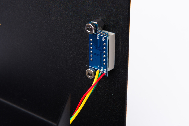
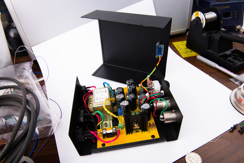
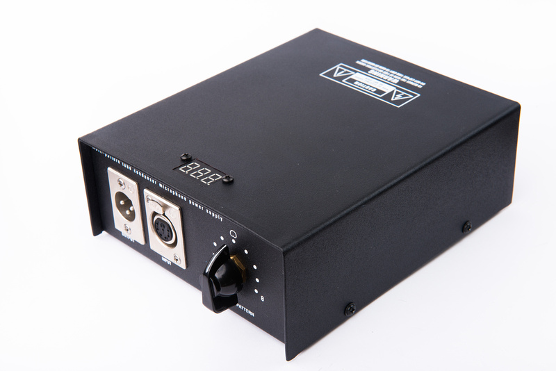
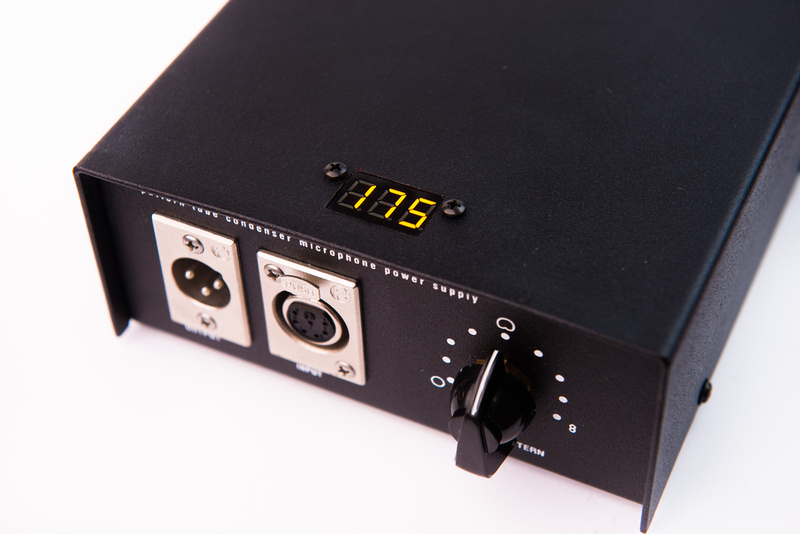
Matador said:Measuring the polarization voltages is at beast approximate: the high impedances make measure these with regular DVM's inaccurate.
For example, measuring the polarization voltage right at the PSU "P3" node will cause the meter current to drop across R11 (1 MEG). A 10MEG meter will induce a 10% voltage error. A 1MEG meter will cause a 50% error.So a 10MEG meter will always measure 60V (the cardioid setting) as 54V due to the meter impedance alone. 120V will measure as about 110V. The bias node "P4" has a similar problem caused by R5, however a 10% error on 1V is only 100mV.
If you know your meter impedance you can "derate" the reading.
You can't measure anything on the capsule, because the meter current will go across the astronomically high impedances and clobber the results: think of a 250M / 10M voltage divider: the series resistance will clobber 97% of the measured voltage.
barbaroja said:Well this has been a little troublesome for me. Fluke 115 DMM, 10M. B+ is 110V. In the middle of the knob switch (cardioid setting), I get: Immediately 50V, if I let it sit, goes down to 47 and stays there. Do I have a problem here?
Matador said:barbaroja said:Well this has been a little troublesome for me. Fluke 115 DMM, 10M. B+ is 110V. In the middle of the knob switch (cardioid setting), I get: Immediately 50V, if I let it sit, goes down to 47 and stays there. Do I have a problem here?
No problem: the RC time constant for the polarization supply is about 2 seconds: 5 time constants is on the order of 10 seconds for the voltage to stabilize.
Remember that the polarization supply is 5M of resistance: so adding 10M means that the equivalent resistance falls from 5M down to 3.3M. Even this lower resistance still has a ~1.5second time constant, so the moment your probe hits the circuit it will take 5-6 seconds for the new voltage to stabilize.
Matador said:Yes you should see 54V with a 10M meter, however that assumes that the resistive divider is exactly 50% at the cardioid setting. The resistors have an additional 1-4% error as well.
I would set your meter to resistance mode, and check the resistance of each half of the resistor string to make sure exactly half of the resistance is on the top and half on the bottom (wrt. ground and B+). I bet you just have a few % error based on resistance tolerance for the polarization string.
E.g., set one probe to ground, and the other to the center of where the polarization switch attaches to the PCB. You should see the resistance change as you click the switch around (from 0 ohms at one extreme to 4.7M at the other).
Matador said:Are you probing where the grey wire attaches? Or where the polar signal goes out to the microphone?
barbaroja said:Black lead: P6 screw (output block). Red lead: Center polar switch block screw, (grey cable, middle one). In omni, I read zero ohm. As soon as I flip the switch to the next step to the right, starts changing readings. After 10s, it settles to 343Kohm. Next switch move is close to 600Kohm. Next goes around 777Kohm. Switch in cardioid is around 860Kohm.