op amp to tube conversion ?

GroupDIY Audio Forum

Help Support GroupDIY Audio Forum:

This site may earn a commission from merchant affiliate links, including eBay, Amazon, and others.

skal1

Well-known member
Joined
Jun 4, 2008
Messages
1,290
Location
Birmingham,uk
Hi all

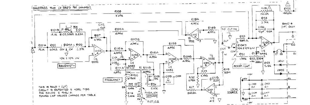
i have just brought an parametric eq, and i was wonder if i could take out the op amps and build a tube circuit for the op amp function.

Its a basic eq with bandwidth ,freq with cut and boost

As i understand it, op amps are just amplifiers, correct me if i am wrong.

would this be to complicated for a newbie ...
 
Tube Tech has a vac opamp also.

Yes there are schematics available.

Looks kind of like Fred's , only different.
 
How many opamps are you thinking about replacing with tube opamps? If the opamps are part of the filters, I would just leave them alone. Replace any amplifier circuits with tube opamps. But what your considering will not be simple. I would have to go look at the Forssell tube opamp circuit again. But most tube opamps do not have very low output impedance. So driving certain loads is going to be very difficult. That is one of the advantages of IC opamps. They have low output impedance and most of them will drive a heavy load without too much trouble. I hope there's lots of extra room inside this EQ box. Because you're gonna' need it. DW.
 
ok ,here is the schem, http://i51.photobucket.com/albums/f392/skal34/6b42-1.jpg

what i was thinking ,i could just join the legs to the correct pins with jumpers at the op amp ,and place the tube pre amp after the filter section , are the op amps interactive with the filter i don't know can some tell if they are this would make the job easier.

this could be an option for the pre , i would remove the riaa filter ,woulld this be ok , if the circuit was not balanced like pultec filter stage.

http://www.geocities.com/rjm003.geo/rjmaudio/images/p6dj8_cir.gif
 
if you possess the enthusiasm to build tube op-amps, why not just build an EQ from scratch?
Is there room in the box to cobble in a power supply and tubes?
Maybe design a Valve OpAmp module with miniture tubes or nuvistors that has its I/O pins broke-out to a DIP header that will plug in to the silicon opamps footprint.
Definite mechanical design challenge... build 1 VOA and see if it works in circuit before you get too ahead of yourself.
Why not build a simple tube make-up gain box...MILA maybe--a proven design.
Maybe read up on EQ's in the meta--learn about the different topologies so you can look at the schematic and know what it is.
 
OK, i think every ones got the wrong end of the stick.


1}i want to bypass the op amp on the board

2} then replace op amp with tube pre amp


3} yes is it will go in a different case


4} I do not know if the the op amps in schematic interact with the filter section

can someone make this clear to me


regards


skal1
 
1}i want to bypass the op amp on the board
you want to remove opampS from board and put sockets if not already there.
(so you can put it back the way it was)

2} then replace op amp with tubepre amp
you need to replace opamp with tube opamp; one with inverting (-) and non-inverting (+) inputs


3} yes is it will go in a different case
is the capacitance and hum pickup of all the interconnects going to make this thing noisy or oscillating?


4} I do not know if the the op amps in schematic interact with the filter section
the opamps in the schematic ARE the filter section of 1 band; probably not the ones you want to tubify

can someone make this clear to me
I don't know.
 
so this means the op amps in the circuit are interacting with the filter, ok then i shall leave these amps and graphed the tube stage at the output , don t know is this a waste of time?

regards


skal1
 
A schematic would be nice, unless it's top secret.

Why not use the standard Pultec line amp?
Going into the input transformer gives you your + and - inputs.

Then you are ready for the stock Push-Pulll circuit.

How much gain do you need?
 
"is it a waste?"
I don't know, if you approach it the right way you can learn something...if you build something useful, it is definitely not a waste. If you destroy a peice of gear in the process...maybe?

build yourself a pair of valve based opamps that pass signal and amplify correctly...you can graft these on as output buffers in the worst case.

but first play with them.
try configuring something like this
http://www.opamplabs.com/325eq.htm
where the 'R's will be a linear pot maybe 100k
and the 'z's will be LC networks
http://circuitcalculator.com/lcfilter.htm? --for instance.

this is good food for thought, and has a pcb layout--(one i etched and stuffed years ago but have not wired up yet. )
http://www.dogstar.dantimax.dk/tubestuf/sapindex.htm
 
the schem is above but i will put it here

6b42-1.jpg
 
hum , definitely a lot of knowledge to take in their , it seems i would have to fab a circuit for each filter bank ,its a lot of work just to turn a op amp based eq to a tube base one .time would be better spent designing a new eq, but i can take this away and play with the idea...

thanks for every ones input


regards

skal1
 
I t looks like 90 percent of the circuit is the opamp and supporting components.

It might be easier just to build something from scratch.
 
There's six op-amps there, doing various things to filter the audio band and bend frequency response.

(The seventh opamp IC101A is fixing DC leaks, and not essential; basically it is cheaper than a large cap.)

"This is band 1 (LF), Circuit is repeated 3 more times."

OK, now we need 24 tube op-amps.

The classic B-B tube opamp module used two tubes. We are up to 48 tubes. 96 for stereo.

As scaled, several opamps are driving few-K loads. The usual tube opamp expects loads nearer 100K. This means a real redesign of the filter R-C values, or a third tube in each op-amp.... 72 tubes for 4-band mono.

There must be better ways to skin your cat.
 
There is one thing that might give you a win, that is replace the IC's with old school Signetics NOS chips.

Unless of course, that is what you have already.
 
hum, thanks for the insight ppr .It seems that a true tube parametric eq is a monster build ,so other name brand eqs sporting the words tube are not true tube eqs but just using the topology to sell products.


SO essentially it is to expensive to make a true tube eq , so company's just graph a tube or two to the out of the filter section and call ti a true tube eq .


regards

skal1
 

Latest posts

Back
Top