Open Source Digitally controlled Analog Project...

GroupDIY Audio Forum

Help Support GroupDIY Audio Forum:

This site may earn a commission from merchant affiliate links, including eBay, Amazon, and others.
iampoor1 said:
The problem with a project like this is defining its scopes and limitations.  ;D

The relay control approach is right for some applications, the VCA approach is right for some applications, and the Digital pot is perfect for some applications (AD5290 is the best I know of).

It might make sense to implement all of these as possible options, within a framework, and then develop it bit by bit (no pun intended)

Also, my vote is for NRNP midi.... 14 bits is enough resolution. There are enough challenges with implementing something like this in the first place, no need to reinvent the wheel......

DPOT is 8-Bits, 14-Bits is Overkill

the logic thing to do, is to use 2x CCs for 1x DPOT,
CC#        0-127 for 0~50%
CC#+1  0-127 for 51%~100%.
but that can create opposing forces.
works like a Non-RAID BIG/SPAN architecture.
https://en.wikipedia.org/wiki/Non-RAID_drive_architectures

or maybe:
CC# Pair
CC#+1 Impair,
alternating values like RAID 0. "Stripped"
but automation would be too much complicated, drawing a simple curve would be almost impossible, without a pair/impair splitter.
https://en.wikipedia.org/wiki/Standard_RAID_levels#RAID_0
https://en.wikipedia.org/wiki/Nested_RAID_levels

there are only 127 CC per Channel = 64 DPOTs or Relays per MIDI Channel, 16-Channels per MIDI Port...
but...
DMX machines use Channels for features, and CC ranges for On-Off features.
DMX Values table:
https://www.chauvetprofessional.com/wp-content/uploads/2015/07/Q-Spot_260-LED_QRG_Rev-02-1-30-12DEC.pdf
https://www.chauvetprofessional.com/wp-content/uploads/2015/07/Q-Spot_260-LED_UM_Rev-02-1-30-12DEC.pdf

DMX is a similar 8-Bit architecture.
to control multiple DMX lights, they must be split in channels...

if i have 1 machine with 8 channels, and 2 with 16 channels...
one possible DMX configuration is:
1-8 HW1
9-25 HW2
26-42 HW3.

the number of channels each machine uses is fixed, some activate or deactivate advanced mode, 8-channels basic, and 8-optional.
but the value/number of the channel group is dynamic,
and the order of the channels is continuous.

SCSI uses 1 Channel = 1 Machine.

Using same HW layer as MIDI, but different compatible protocol...
some MIDI interfaces are Not multi-client,
that means if you have Protools or Cubase or Logic, or Ableton, etc...
the MIDI interface is busy...
and cannot be shared with other softwares,
assuming the HW control software is Stand alone,
but that depends on the MIDI interface driver design...
RME hdsp 9632 MIDI interface i think is multi-client...

real midi ports are definitely better than USB Midi ports.
Lan rtpMIDI is definitely better than USB Midi ports.
 
Juanpcdiy said:
DPOT is 8-Bits, 14-Bits is Overkill

the logic thing to do, is to use 2x CCs for 1x DPOT,

That's exactly what do RPN/NRPN...
+two CC to set the NRPN number

you end with 16384 parameter of 14bit (16384steps) that's what midi can do since decades (if manufacturer/developer bother to fully implement midi spec...)

Some Dpot go up to 10bit... NRPN do it easy with stepped LSB  (MSB  0 to 127 + LSB 0/15/31...111/127 ) or non full scale use of first 1024 value (MSB+LSB from 0 to 1023)

Best
Zam
 
Yes...14 bits is overkill, but 8 bits is underkill. VCA's can have a much finer resolution than a DPOT, and Dpot resolution is surely going to improve with time. Many DPOTs go up to 10bits already. If you are trying to build a "standard" do not start with the absolute minimum resolution when implementing a 14bit interface is not much more work! :)
 
I don't understand why you still consider MIDI (vs.  OSC). OSC would be much better fit in this kind of use case which is to control analog devices. Like there's tons of software which to integrate easily. For an example check these free SW libraries:

OSC VST bridge:
http://oscvstbridge.sourceforge.net/
-VST plugin for OSC

https://github.com/CNMAT/OSC
- Arduino and Teensy OSC library

TouchOSC:
https://hexler.net/software/touchosc

Grab those, and what ever hw control mechanism (VCA, digital pots etc.) you ever want to use you can implement using Arduino or Teensy board connected to your HW and control, at least on prototyping level, using the above VST plugin. I think Ableton Live specially has good support for OSC (https://www.ableton.com/en/packs/connection-kit/ etc.). MIDI is outdated, it's OK for playing keyboards but not for much else. OSC uses similar resource based  URL's as all web applications today (which use REST API's). So the OSC API itself descibes the parameters and resources that can be controlled in cleartext format, for MIDI you need complex MIDI implementation charts and hundreds of pages of documentation telling which RPN/NRPN control which parameter on HW. Also the whole OSC ecosystem is growing all the time, for MIDI application you have to dig a lot to find anything usable.

E: The VST plugin above might not be the solution for current 64-bit DAW's but you get the idea anyway. Also regarding the datatypes the basic OSC datatypes are 32-bit fixed or floating point number for and example, or strings. There's simply no rationale in thinking how many bits to use, seven, 14 or something else, just send some numbers.

 
Non-Invasive solutions already been done:
https://yostlabs.com/servo-center/

USB to Servo,
MIDI to Servo.
$100us. each.
 
Look again.

It's not the servos that present the problem (I diy'ed my first working cnc-machine around 1999), but the universal mechanic interface to pots and switches. 

You should really do a working and universal mechanical model before starting worrying about resolution and software. All that is already done, as you see from previous comments..

Jakob E.
 
Non-Invasive CONS: too expensive...

The fastest Servo from Futaba BLS-276SV $180usd. + SH
GearBox to convert 90° to 360° $100usd. + SH  "but only works well with servos that can be reprogrammed."
https://www.servocity.com/bm-400-400-servo-gearbox

Cheapest Linear Servos $90usd. + SH
https://www.servocity.com/servos/linear-servos
Pro Linear Servos $300usd. + SH

Controller Board MIDI to 16-Servos $81usd. + SH "Expandable"
https://yostlabs.com/product/servocenter-midi/

to convert / digital control 16 Pots a "A Basic Analog Rack"
============= $4561usd. + SH Parts Only, more are needed, probably ~$5kusd.

The Gear Box cannot be avoided,
using a slower / cheaper servo can also work.

Slowest Standard Size Futaba S9151 Servo: $90usd. + SH
x16 = $1440usd. + SH
+ 16x Gearbox = $1600usd + SH
+ MIDI Controller
======== $ 3121usd. + SH for 16-pots.

Speed & Accuracy is important with multiplier Gearbox.

purchasing fake Futaba, saves cost, but are Not as accurate, they shake like Parkinson, some ACME brands are very good.
Futaba cost is prohibitive...
there are others more "price / performance" balanced ratio,
Fastest to Slowest:
Futaba BLS-276SV $180usd. + SH https://www.servocity.com/bls-276sv-servo
Futaba S9254 Servo $110usd + SH https://www.servocity.com/s9254-servo
Futaba S9452 Servo $85usd + SH https://www.servocity.com/s9452-servo
Futaba S9151 Servo: $90usd. + SH https://www.servocity.com/s9151-servo

Savox are way cheaper, $32usd, the slowest $65usd. the fastest.
https://www.servocity.com/sc1258tg-standard-size-coreless-digital-servo
Speed, Accuracy, Repeatability & Reprogramable is Unknown.

Hitec servos, depends, can be cheaper than futaba or more expensive.
some do Not work with Standard PWM signals...
The PWM range for this servo is 760 ~ 1020 usec. It will not work with servo controllers that transmit a standard PWM range (1050-1950usec). Hz Refresh rate: 200~560 Hz.
like the: https://www.servocity.com/hsg-8315bh-servo

The slowest Standard size servo from Hitec $60usd. + SH
https://www.servocity.com/hs-645mg-servo

Some have Back flow current, that requires a PAD in the circuit:
PLEASE NOTE: While compatible with most radio control devices, the regenerative braking feature of the HSB-93XX series servos may cause a problem if the device cannot accept a backflow of current. The types of devices that cannot accept this backflow are: Voltage Regulators, Power Safe Receivers and certain BEC circuits whether stand alone or integrated within an Electronic Speed Control. Check with the manufacturer or the Hitec website for a list of compatible models. If your device cannot accept a current backflow, then you must install a PAD (Power Absorbing Device - Hitec PN# 55756) as described in the manual. A PAD is included with every Hitec brushless servo.
like: https://www.servocity.com/hsb-9360th-servo
$210usd. + SH

https://www.servocity.com/hs-7940th-servo
$150usd. + SH

while its a nice idea, it becomes price prohibitive / too expensive..
PROS:
can be purchased piece by piece, upgraded piece by piece, a big investment to start is Not required.
Different kinds of servos can be mixed, some are more important / critical than others.
Input & Output gains speed is usually Not important, but precision is.

to be continued=?...
 
zamproject said:
Hello

Did you ever try to install a PWMed motor in an audio device ?
You'll have issue with noise...

Best
Zam

Non-Invasive = Outside the Box,
the Box is usually metallic / electric conductive.
the Box is usually connected to Ground.
= https://en.wikipedia.org/wiki/Faraday_cage
 
Even being out of the box, it doesn’t seem the most efficient solution.

I think Wes Audio has a nice solution for this, they even adapted it to a classic design as the 1176 compressor.

Wes Audio protocol is kind of open, I don’t recall the exact conditions but I got some tech documents easily.

I think RJ45 or even wireless is the way to go if we’ll deal just with control signals and keep audio analog. WiFi or Bluetooth antennas are cheaper than cool vu meters nowadays.

I have some clear ideas about where would I go with this, just need time to study...
 
Perhaps the best way of looking at this is to think of the software implementation as one cohesive standard that could then suit various hardware control systems from various makers and manufacturers.
These systems have become more and more popular over the years and having a standard for them wouldn't be unprecedented. If we could supply an open software standard and create a few hardware implementations (some more invasive than others, some which could be built in to hardware at the design stage, etc) people might find a total recall system worth it.
 
taczowbes said:
Perhaps the best way of looking at this is to think of the software implementation as one cohesive standard that could then suit various hardware control systems from various makers and manufacturers.
These systems have become more and more popular over the years and having a standard for them wouldn't be unprecedented. If we could supply an open software standard and create a few hardware implementations (some more invasive than others, some which could be built in to hardware at the design stage, etc) people might find a total recall system worth it.

To me thats called MIDI or Ethernet...

anyway...
Part 3... converting Real VU/Led Meter signal to Digital MIDI or Ethernet data, to make a VST AAX or Stand alone GUI with true VU/LED signal from the Real Analog HW, with minimum latency.

Most VU Meters are 90° and Current type, Not voltage type...

goal #1. is to measure the voltage & current of the VU meter,
without affecting the VU meter...
that means very high impedance 1Meg ohm minimum, 10M better.
circuit will be similar to a hi-end DigitalMultiMeters.

https://www.youtube.com/watch?v=JbCI4Lsnqho
https://www.youtube.com/watch?v=wbRx5cQZ8Ts
http://www.tonnesoftware.com/meter.html
https://www.youtube.com/watch?v=4U-nxdp-LDw
https://www.youtube.com/watch?v=6obMgUC5FKs
https://www.youtube.com/watch?v=7OLGswQ7ICI

----
DMM
https://youtu.be/yuCXsT3_WRE
https://youtu.be/UKIzhz0XLaQ
https://youtu.be/g3uYcHAumhA
https://youtu.be/6j8i3LfKm5A
https://youtu.be/e9cpKN69Avk

goal #2. to use common / low price AD converters...
8-Bit 256 steps for 90° could be good enough.
0.3515625° per step, but MIDI CC has 7-Bit = 0.703125° per step..
MIDI also allows 14-Bits but its over kill for an 8-BIt AD.

Candidate #1: YL-40 board with Philips / NXP PCF8591T
PROS:
has:
4x AD
1x DA
SCL
SDA
GND
VCC
Temp, Light, Manual Pot Volt meter. "probably will never be used."

problem/Cons: is 3.3vdc.
most analog hardware works at +15/-15vdc, VU meters are Rectified DC witha Schoky or fast Diode 4148 glass type.

the voltage resistor / divider network circuit requires very high-quality precision resistors.


Part 4.. Building a Relay Network Matrix. "like a 12v Relay FPGA."

Candidate #1: 16-Channel Relay Module.
https://einstronic.com/wp-content/uploads/2017/06/Relay-Modules-Catalogue.pdf
there are 2 versions of the board, one comes with a 12v to 5v buck converter,
the other, the buck converter is unpopulated in the PCB, apart from that, are exactly the same.
the populated version requires +12vdc for the Mechanic Relays & +5vdc for the Opto Couplers and the Darlingtons to puch the Relays.
the unpopulated version comes with +5vdc Relays, JQC-3FF-S-Z

why mechanical vs. solid state like: omron g3mb-202p
or other CMOS, JFET, or BJT ?

mechanical guarantee absolute signal integrity... some BJT affect signal...
must have very low on resistance if Solid, like IRF510,.

alternative a Vacuum tube switch matrix maybe can also be done, for fun... like a Thyratron or a SCR.
https://youtu.be/ygg04-DIXj4?t=352

PROS: High switching speed Not required.

The Matrix is required to Route any analog or digital signal, like a Remote Controlled Patchbay...
like Solid State Logic SSL X-Patch,
but the problem with SSL X-Patch is that signal path is Not passive, its Active and has Audio Buffers at the input. "Op-Amps"
that does Not allow to route any signal,  like AES/EBU, Wordclock, microphone, turntable. for example.

if the Matrix Relay is done with MIDI & Ethernet, the Ethernet port maybe can be designed to Emulate  SSL Ethernet port,
and may be compatible with SSL software.
http://sslweb.solidstatelogic.com.s3.amazonaws.com/content/x-patch/XLogic_X-Patch_Install_Guide.pdf
http://sslweb.solidstatelogic.com.s3.amazonaws.com/content/x-patch/XLogic_X-Patch_User_Guide.pdf
http://sslweb.solidstatelogic.com.s3.amazonaws.com/content/x-patch/X-Patch_Remote_MAC.zip
http://sslweb.solidstatelogic.com.s3.amazonaws.com/content/x-patch/X-Patch_Remote_PC.zip
http://www.solid-state-logic.co.jp/docs/X-Patch_Flyer_jpn.pdf
http://www.solid-state-logic.co.jp/music/Xlogic%20X-Patch/images/X-PATCH_Performance_large.jpg
http://www.solid-state-logic.co.jp/docs/X-Patch_connections.pdf
http://www.solid-state-logic.co.jp/music/Xlogic%20X-Patch/images/X-PATCH_16_CH_Inserts_large.jpg

its a 16x16 Patchbay, but software allows to control 6 units more.
https://www.barryrudolph.com/mix/sslx-patch.html

Ethernet Shield v1 with W5100 is required because  W5100 doesn't come with a pre-assigned MAC address.-
Ethernet Shield v2 with W5500 is No Go.
there are other Ethernet modules like: ENC28J60 with SPI interface, but MAC address is unknown.
https://github.com/njh/EtherCard
https://www.instructables.com/id/Arduino-Webserver-Controller-Using-Ethernet-ENC28J/
https://blog.japaric.io/wd-4-enc28j60/
https://www.luisllamas.es/arduino-ethernet-enc28j60/
http://ww1.microchip.com/downloads/en/devicedoc/39662e.pdf
 
Juanpcdiy said:
.
Part 3... converting Real VU/Led Meter signal to Digital MIDI or Ethernet data, to make a VST AAX or Stand alone GUI with true VU/LED signal from the Real Analog HW, with minimum latency.

Most VU Meters are 90° and Current type, Not voltage type...

goal #1. is to measure the voltage & current of the VU meter,
Wrong; although VU-meters are indeed current devices, they are used to measure voltage. You want to know the amplitude of the audio signal, you measure its voltage. Now VU-meters are obsolete in the context of digital recording. You want Peak-meters.
 
other Matrix with Total Recall is the:
https://www.tegeler-audio-manufaktur.de/Konnektor_analogue_mastering_matrix
more advanced that SSL X-Patch...
https://youtu.be/WnW367c5unw

https://www.tegeler-audio-manufaktur.de/Schwerkraftmaschine_der_Kompressor
has Motorized Pots.

https://www.tegeler-audio-manufaktur.de/News/Why-We-Chose-Ethernet-instead-of-USB-FireWire-Thunderbolt-MIDI

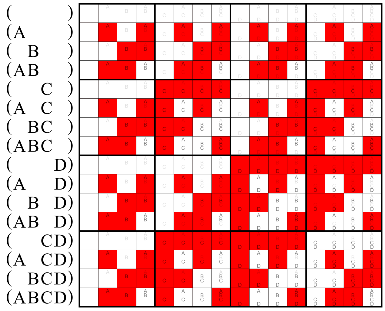
1270px-Multigrade_operator_XOR.svg.png

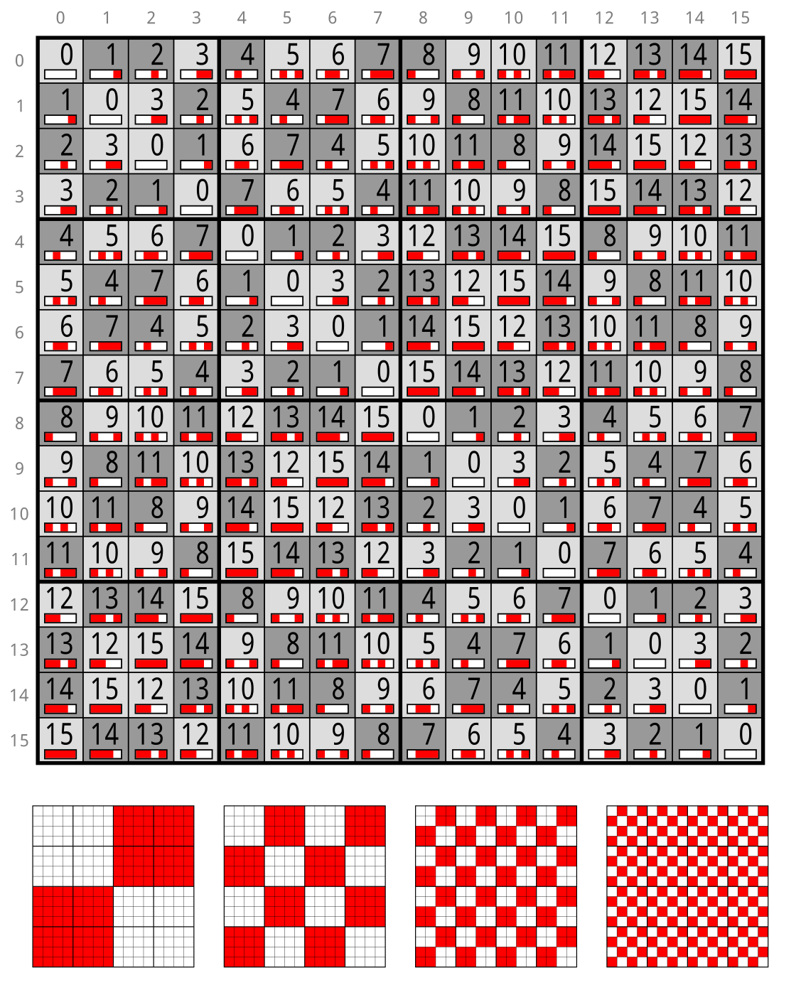
1127px-Z2%5E4%3B_Cayley_table%3B_binary.svg.png
 
abbey road d enfer said:
Wrong; although VU-meters are indeed current devices, they are used to measure voltage. You want to know the amplitude of the audio signal, you measure its voltage. Now VU-meters are obsolete in the context of digital recording. You want Peak-meters.

#1. This thread is about mimic a Real Analog Hardware User Interface including VU meters if Real HW Has,
with a Digital Graphic User Interface in VST, AAX, or stand alone.

Not about cheating  Vu Meters, its about measuring the Real Hardware VU Meters "if has", in Real Time and display the exact value as close as possible "within digital limits", the Real Hardware with a GUI inside a DAW.
to allow Analog Hardware to be Digitally Controlled with GUI feedback..
---
#2.
ive done tests with different DAWs, Protools HD 10, & HD12.7, Logic 9, Cubase/Nuendo3/4, VSTHost, Ableton, Samplitude, Cakewalk Sonar, etc...
3rd party plugins from Waves, PSP Audioware and others,
and Digital Hardware like Tascam DM-3200 digital console with Real Leds meter bridge ...

most Software Meters are useless.
Logic 9 the worse...
Tascam digital console, the best ive seen.
to me software are Not close to real hardware...

i haven´t done test with Waves Durrough Meters, they claim they are exactly the same, with side by side video...
but Waves VU, Not as good to real hardware.

PSP Audioware Triple Meters are very strange, the needle jumps, like if the screen has 15frames per second, very weird,  like Midi 7-Bit jumps.
Logic 9 meters are so bad its mind blowing, compared to Tascam digital console real Led meters... with same signal, its mid blowing.
---
#3.
i know there are more Advanced Digital meters, like Dynameter, TC Electronics LM, etc...
https://youtu.be/HW8Te1KqZrg
https://youtu.be/rQa6xOo-xEs

https://youtu.be/3Gmex_4hreQ
https://youtu.be/scfmFbA3DwA?t=125

to me Real Vu Meters are more important Now than ever/never...
 
I've got a bunch of motorised faders and encoders ready for a project similar to this. I've experimented a bit with various mixers. Keeping motor noise out of the audio isn't easy. And keeping PWM out of the audio seems next to impossible if you replace normal faders in existing gear with motorised ones.

The talk about servo's gave me an idea. Take an ESP8266, a Lipo battery and a reasonably strong mini servo. Add a few FETS for a H-bridge. Put into a case, with a rubber snap-on for the usual knobs. Could work for externals, is reasonably universal, as long as you have different rubbers. Won't break the bank...

Even cheap enough to build several.

Only problem is: How do we keep them in place?

Rubber bands? Clamps? Suction cups? Framework? Magnets?

Magnets seem interesting, until you consider they don't work on aluminium fronts...
 
Juanpcdiy said:
#1. This thread is about mimic a Real Analog Hardware User Interface including VU meters if Real HW Has,
with a Digital Graphic User Interface in VST, AAX, or stand alone.

Not about cheating  Vu Meters, its about measuring the Real Hardware VU Meters "if has", in Real Time and display the exact value as close as possible "within digital limits", the Real Hardware with a GUI inside a DAW.
to allow Analog Hardware to be Digitally Controlled with GUI feedback..
So you want your software to mimic the errors of a mechanical VU meter. What's the use?

most Software Meters are useless.
Often the reason is that graphic tasks are given a low priority compared to audio.
I use the meters of the Tascam DM4800 and I find them useful, although they don't show intersample overs. The meters in Samplitude or Reaper are just signal presence indicators.

{quote] i haven´t done test with Waves Durrough Meters, they claim they are exactly the same, with side by side video...
[/quote] They may be, but what's the point? VU meters are inadequate in the context of digital audio.

i know there are more Advanced Digital meters, like Dynameter, TC Electronics LM, etc...
Most of these meters are designed to provide more useful and more adequate information than a mechanical VU-meter. They are mostly designed to provide quasi-peak information.

to me Real Vu Meters are more important Now than ever/never...
Important in what respect? What is the unique information they give? I've had my share of dealing with VU-meters; after 50 years of using them, I admit they're good for two things: alignment of equipment using steady tones, and as a crude indicator of signal presence.
 
I agree with Abbey as usual.

The Dorrough meters  were inspired (cough) by my patented Peak/VU meter system (US04166245  Roberts 1979). Dorrough changed the nomenclature and curved the display to finesse infringement of my earlier patent that used a straight line display and plainly described the signal attributes (peak/ave).

Peak and average can both be important signal characteristics to separately manage headroom and relative loudness while mixing.

VU meters are more fun to look at. I even put twenty four plus old school VU meters in one AMR console meter bridge (1990s), because the customer is always right, even when wrong.  ::)

JR
 
Update:

was testing in ProTools the speed of "generic servo MG996R" http://www.towerpro.com.tw/product/mg996r/
there are 2 versions, 1 continuous "360º", the other Range Limited to 120º, BUT... physically can go 180º..
thats problem #1.

Problem #2. is that the Servo Midi v1.2 Board, has a LM1084 5Amp Regulator, BUT... does Not have current limiting resistors on each Servo Output...

i had only 1 servo connected receiving the full 5Amp load...
Servo MIDI Controller Default Range is 0-127, cc114 cc115, BUT... that range forces the MG996R Servo to go beyond 120ª, beyond 180º
When Servo is forced to Hard Limit, overheats and burns...
was sending a 1010101010111111 Midi signal

i thought the servo had an internal built-in current limit resistor inside, or some kind of protection, but does Not...
thats why is so cheap. LOL Jajajajajajaja lasted 5 minutes.

the Servo datasheet says its designed for 500mA, x16 = 8Amps.
but LM1084 is 5A
the solution would be to install LT1083 that has more current, but small heatsink, also needs to be improved.
the LT1082 is 5 pin Not compatible.
but the Board can also be used with external power, and disable internal servo power, but the external power input connector does Not feel bold / robust enough, as only source, as helper is ok.

purchased another servo, ohm resistance is: 2.3ohms aprox. burned servo shorts the motor 0.ohms.

the Servo Midi board is based on ATMega8515L
but code has some problems...

allows Servo Output s0 to be Midi controller by cc0 in Low Range jumper Setting, and cc16 in High Range Jumper Setting...
But ProTools HD12,7 Does Not allow cc0, only from cc1 in  Automation... Edit window.
to draw automation, can only be used from servos 2-16  "s1-s15" OR... jumper must be changed to High setting cc16-cc32 in the pcb...
that is a No go, code must be modified for ProTools...

Add/Remove Controller from the controllers submenu Range Goes from cc1-cc119 for Automation... in Edit mode.
Midi Event List can edit all the missing controllers.

maybe creating a custom Midi controler in OSX Midi Studio... maybe...
 

Latest posts

Back
Top