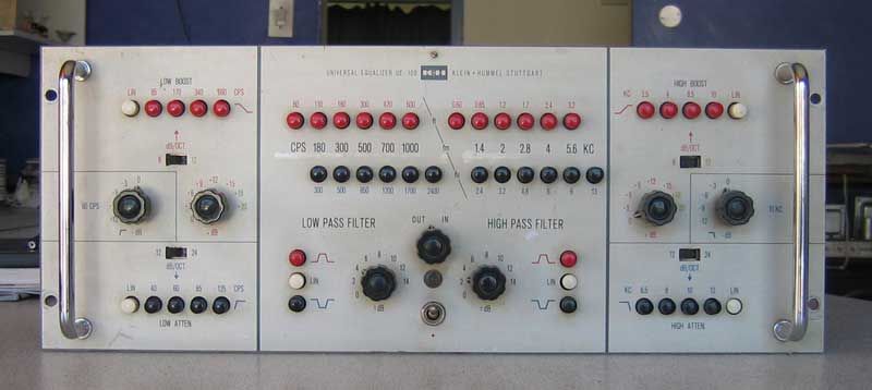
Here's something that's going around in my head for some time.
Think of a typical passive EQ with a L C series connection to create a bell courve.
Usually, you have a rotary switch to select the center frequency, the switch connecting different L and C values to the circuit.
We all know the center frequency is calculated as fc = 1 / (2 Pi SQRT(LC)).
For a certain center frequency, we have multiple choices. We can pick an L value, and then calculate the C value accordingly.
But there's also the Bandwidth, or it's inverse, the Q value. So depending on the impedance of the rest of the circuit, and the Bandwidth you want, you must choose a specific L value *and* C value. In other words, with the product L * C being constant (for a certain center frequency), a higher L (and lower C) gives you a higher Q factor, and smaller Bandwidth.
Some passive EQ circuits have a variable R in series with the L and C. This is a means to vary the Bandwidth while keeping L and C constant. Unfortunatey, this also means that you normally get less cut / boost range at higher bandwidth than at smaller bandwidth.
This is nothing new so far - I just tried to sumarize the situation without being too technical.
Now I think of this: We could have much better control over Q (and Bandwidth) in a passive EQ, if we use *separate* switches to select the L and the C values. One could start with the typical values of a commercial EQ of rather high Q factor, but instead of adding a variable resistor in series with the L and C, we could simply switch Ls and Cs with two separate rotary switches.
The problem is just, how to label this switch.
I can imagine 3 ways to do this:
(1) Engineer's method (bad) :? :
Just write down the C and L values. One switch to choose your Nanofarads, one switch to choose your Millihenries.
(2) Overkill method (overkill) :shock: :
Use a bank of relays, and some control logic, then you can choose fc with one switch, and Q with a second switch.
(3) Pseudo-Frequency method :idea: :
Label both, the C selector knob and the L selector knob in frequencies.
If you want the "nominal" Bandwidth at 1kHz center frequency, set both switches to 1kHz. Want to increase Q factor, set turn up to C "frequency", and turn down the L "frequency" by the same number of positions.
Example:
1kHz, nominal Q: C-Switch = "1kHz", L-Switch = "1kHz"
1kHz, higher Q: C-Switch = "2kHz", L-Switch = "500Hz"
1kHz, even higer Q: C-Switch = "4kHz", L-Switch = "250Hz"
1kHz, lower Q: C-Switch = "500Hz", L-Switch = "2kHz"
Looks complicated? It isn't. Just start with 1kHz on both knobs, and then move one up and the other down by the same number of steps.
Does this make sense? Has it been done before?
JH.


