PCBs for 1176-flavoured FET compressor w/ opamps - (almost) no wiring

GroupDIY Audio Forum

Help Support GroupDIY Audio Forum:

This site may earn a commission from merchant affiliate links, including eBay, Amazon, and others.
scott2000 said:
Are there considerations if using different colors???

No, shouldn't be a problem.

I just noticed the picture in the top of the thread looks like the metering is going from right to left??? Is this true??? Is that an aesthetic decision because of the knobs in the Hammond case obstructing the view a bit??

Yes, it's from right (lowest compression) to left. A lot of hardware compressors with LED metering have it this way. A popular example would be the Distressor - as well as the Alesis 3630, JBL 7110 or DBX compressors etc.

Maybe it was designed to mimic the needle of an analogue VU meter which also moves from right to left to indicate gain reduction. I didn't really think about it - thought it was common sense 8)
 
Yes, round LEDs will work, too. Flat LEDs look best when they are flush with the front panel and the spacers from the BOM are sized for this purpose. If you use round ones you could take slightly longer spacers, so that the LEDs protrude the panel a bit. This looks better IMO.

35mm caps are fine for the PSU. There's nothing above that board and it fits a 1U case perfectly as well as the Hammond box. But with that said - do you really need 50V filter caps in the PSU?! Depending on your choice of power transformer or wall wart, 35V should be more than adequate.
 
dasnevestheo said:
Any audio samples yet ? i want to hear how it compares to the original and the distressor :)

Here you go :)

Snare @ 4:1
Compressed snare drum. The first two bars dry, then compressed.

Drum Room - Slam mode
Stereo drum room in Slam mode with sidechain filter engaged. Again, clean signal for the first two bars. Remember, I didn't add the link mode to the unit I built, which means that this has been compressed in un-linked dual mono. In this case the controls have to be matched by ear. Still, it tracks pretty good...

Stereo Drum Overheads @ 4:1
Clean signal for the first two bars. This is the OP76 in one channel and my 1176 Rev. D in the other. Obviously they are not linked and the settings have been matched by ear, so that the amount of compression and the timings are about the same in both units. They seem pretty much alike to me 8)

Rock Bass mic'd + DI signal @ 8:1
Two sections of the same song, first clean and then compressed.

Rock Bass mic'd + DI signal - no compression
First section from above. Compression set to OFF with the input gain cranked for some nice and thick saturation.

At last: Female Vocals @ 8:1
This one's giving me the goosebumps. Extremely dynamic female vocal with added reverb. No compression on the way in, just a bit of manual gain riding on the mic pre. Again, starts clean - compressed signal from 2:23 min. It's awesome how this compressor is able to keep her dynamics in check without ever sounding flat or over-compressed.
 
Is it just me or is the newer guide missing some things on the BOM....the 13pin angled header??? maybe  some other things??? I don't have time to look yet ......


edit....looks like a small section maybe got cut off???
 

Attachments

  • op76 missing bom 1.jpg
    op76 missing bom 1.jpg
    40 KB
Good catch - now fixed! Just re-download the zip file. Sorry for the inconvenience.

Thanks for the heads-up!
 
Ok guys, summer (winter?) break is over!  ;)

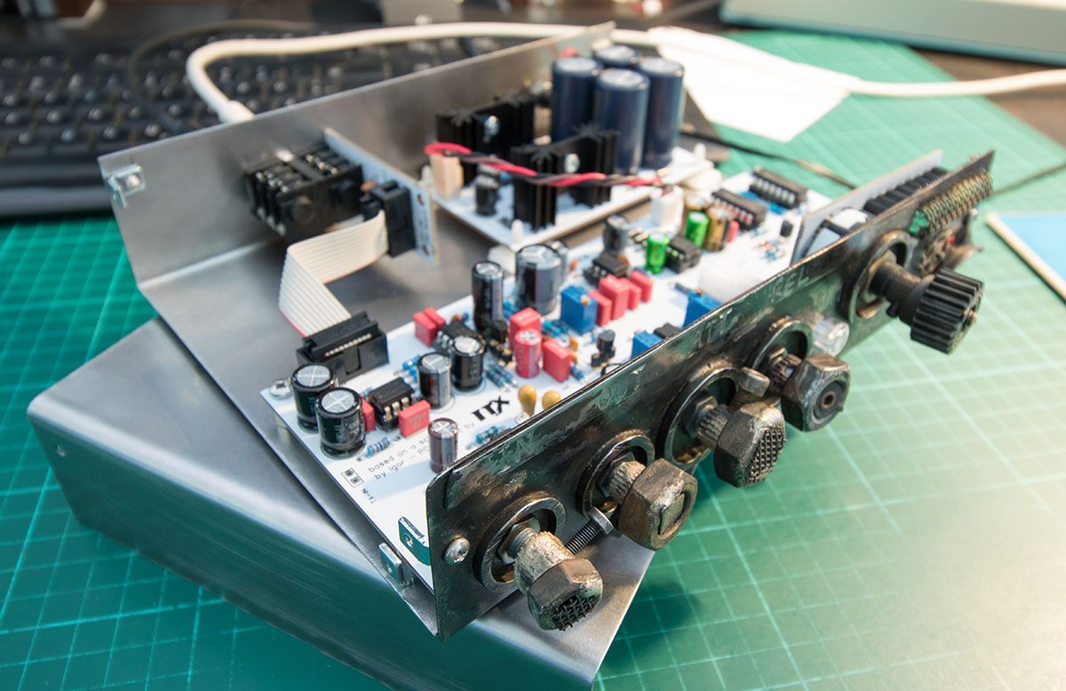
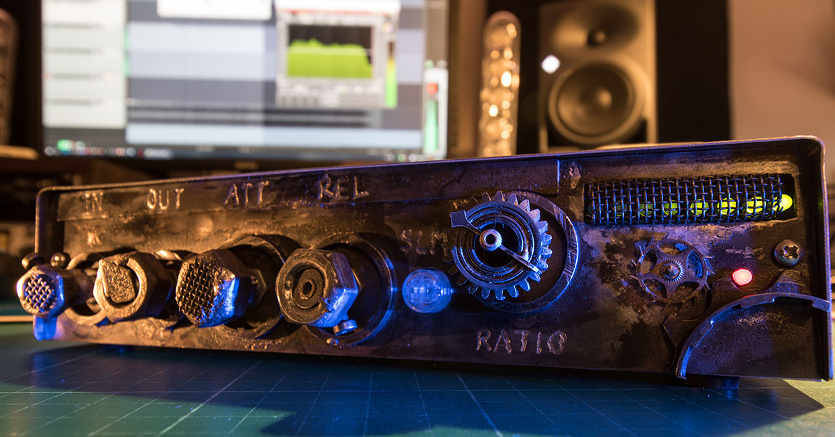
As one can never have to many 1176 style compressors, I've just finished another unit. This time with an entirely handmade steel enclosure - including the knobs. Turned out pretty well... and smells like WD40, mmmh 8)

op76_steampunk1.jpg


op76_steampunk2.jpg


How are your builds coming along? Any photos, stories, questions?

And BTW; I still have boards available ;)
 
Very cool! Steam Punkish.....

My progress is in a box at the moment...I have the main board/s stuffed and have the power supply parts but have been busy and nibbling on other projects..... I see that's how it sometimes goes with the DIY....

Really dig the piece! I was planning on something different as well. ... Square LED bars and such.......

Thanks for sharing!

Any hints or extras on the build or issues you've encountered outside of what is in the manual????
 
Hi Thomas,
I'm almost done.
I get so much support from Thomas with my build. (THANK YOU SO MUCH)
I had some issues with DC at the Output pot because of C20. Reverse the capacitor fixed the problem.
With the second channel I had some issues with my LEDs. They stand still at the 5th.
I used for this board LM339N transistors, after I swapped one out to a LM339AN the LED hang on one.
The LM339 have some different pinouts what I see at the data sheet. Especially the older ones. Could be possible that I buy older ones at the electronical shop. Will see what happened, when I change the second LM339N to LM339AN.
 
scott2000 said:
Very cool! Steam Punkish.....

My progress is in a box at the moment...I have the main board/s stuffed and have the power supply parts but have been busy and nibbling on other projects..... I see that's how it sometimes goes with the DIY....

Really dig the piece! I was planning on something different as well. ... Square LED bars and such.......

Thanks for sharing!

Any hints or extras on the build or issues you've encountered outside of what is in the manual????

Thanks Scott! And yes, I'm currently working on an errata section for the guide which addresses some of the issues that Till was running into. Minor stuff, but with room for improvement.

I will update the guide within the next day or two. Keep you posted.
 
Hi Guys,
finished mine with the help from Thomas.
They sound really good. Thats my first compressor I get working. My Mnats 1176 don't work since months.

I've had problems with the TI LM339N. Don't know whether its a problem general with TI LM339N.
So thats why the first LED on Channel A is on. Must change it to an TI LM339AN, then also this works perfect, like my other Channel.

The design is so solid, and everything fits perfect.
Really, really good bang for the buck project.
Soldering was easy and the parts are not so exotic.


Attachments

  • IMG_3805.JPG
    IMG_3805.JPG
    965 KB
TillM said:
Hi Guys,
finished mine with the help from Thomas.

Well that's awesome!

What power supply configuration did you end up using?

That's interesting on the 339s...... I stuffed mine with several old 339AN pulls I had  so hopefully it'll be ok....

Agree with the ease of soldering. These boards are very nice indeed....
 
I took them with a 9VAC plug.
Works great.


Mine with LM339AN works great.
Thomas also uses LM339N and it works. This problem seams to be just with TI ic's.
Well Scott ... thank you so much vor the pots.
They came even faster then my order from Banzaimusic.
 
I've just updated the guide archive. The build manual now includes the errata section mentioned before.

Just re-download the file linked to in the first post of this thread.

Thanks!

 
changed the last TI LM339N to a TI LM339AN now the meter board works perfect as it should.
Great project and I really like the hammond enclosure.
thanks Thomas !
 
PRICE DROP!

Until December 31st, 2018 the price for one of the OP76 board sets is just 30 Euros plus shipping.
 
So... love the look of this build but I was thinking.... I've got a spare 2-Stage Line Amp board from CAPI (http://capi-gear.com/catalog/product_info.php?cPath=22_191&products_id=438) and I want to try using the DOA as the gain stage for this.

I would use the 2SLA board to go from balanced to unbalanced then send that to the TX-IN, could I then take the signal from C21 and send that back to the 2SLA board for makeup gain?

Also, does anyone have a spare PSU board from a stereo build they would be willing to sell me? Would save me making one for another project I'm working on!
 
Mike Havok said:
I would use the 2SLA board to go from balanced to unbalanced then send that to the TX-IN, could I then take the signal from C21 and send that back to the 2SLA board for makeup gain?

It should work but the input signal would be 6 dB lower with the DOA (the website says it's a -6 dB receiver). You'll be getting slightly less compression/distortion that way.

I happen to have a spare PSU part  ;D
 

Latest posts

Back
Top