Pentode Tests

GroupDIY Audio Forum

Help Support GroupDIY Audio Forum:

This site may earn a commission from merchant affiliate links, including eBay, Amazon, and others.

DaveP

Well-known member
Joined
Nov 8, 2005
Messages
3,114
Location
France
Ever since I read a post by Ian (ruffrecords) about noise, I have been looking at the problem in pentodes.

Some of the early theories about noise in pentodes have been challenged recently, and an article in Linear Audio by Frank Blohbaum showed how it was possible to recombine the screen grid current with the plate current to neutralise partition noise, by using a second device.  I may get around to testing that myself one day, but I thought I'd share some data I produced first.

The partition noise is caused by the splitting of the cathode current between the plate and g2, so by reducing the G2 current we should minimise the noise.  The stuff on forums often says a 6J7 is a 6SJ7 is an EF86 and so on, but I have just found that is not true at all.  They have different internal dimensions which do not allow you to vary the respective currents at will as this table shows:-


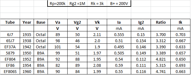
I carefully set up an experiment with exactly 6.3V of DC on the heaters and exactly 200V for the B+.

I used the values for the V76 mic pre because they are pretty much optimal, but I had both plate and G2 resistors at 200V, not as in the V76.

What is immediately obvious is that the screen current has been reduced over time to reduce the partition noise, and the ratio has gone up.  This is one of the keys to a low noise pentode.  I was unable to adjust the earlier tubes to get anywhere near that later ratio.

The gain under the same conditions is in this table:-


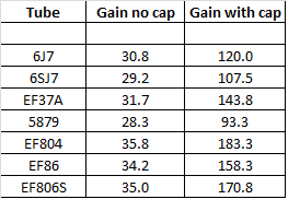
Admittedly, these are only single samples of NOS tubes but there is no way these can all be considered to be equivalent .

I hope you find this data helpful in future projects
Best
DaveP

 
I have little experience of pentodes  but as a rough rule with any tube you can expect a variance of 10% in dc operating conditions between valves of the same type. Looking at your table of dc currents it would appear these tubes pretty much fall within this range even though they are different types..

The voltage and gain measurements clearly are not within 10% however, they are all very sensitive to the load imposed by the measuring instrument. Accurate screen voltage measurements are particularly difficult when the screen is fed via a 1 Meg resistor as is the case here.

Cheers

Ian
 
Ian,
There was no problem getting the screen voltage because it was stabilised with a 1uF cap to ground.

I should have mentioned that the results were taken under ac load, not quiescent.

The object was to show relative differences and there was a 100% difference between the gain of the 5879 and the EF804.

best
DaveP

 
Interesting!
Thanks so much for the data!
Planning on experimenting with some tube stuff this winter, and testing several large boxes of tubes I collected many years ago.
Best,
Bruno2000


I am still not 100% comfortable with your screen grid measurements. The 1uF ac decouples the screen grid. It will not stabilise the dc voltage. Looking at the 89V  you measured for Vg2 of the EF86, the implies the screen looks like 802K to ground at dc. For this to be an accurate reading your volt meter input resistance must be more than 10 times this.

Cheers

Ian
 
Ian,

These are meant to be relative measurements and as such they are fine, but just to put your mind at rest, the input resistance of my DMM is 10Meg so that satisfies your criteria.  When taking the measurement I noticed no perceptible drop, which one would have expected if the cap was discharging through a low impedance.

Best
DaveP
 
I have worked out the rp, gm and mu of these tubes using the feedback formula.

Gain (no cap) = Gain (+cap)/ 1+Gain(+cap)Rk/EPR+Rk

Where Rk =3k and Rp =200k, probe =1M

EPR (effective plate resistance) is 200k//1M//rp

Reversing this on a spreadsheet to get  EPR allows you to use Steve Bench's formula to find gm as Gain/EPR = gm

You can get rp out of the EPR by reversing the parallel formula 1/EPR -1/200 -1/1000=1/rp

When you have rp and gm you have mu, not that it helps much, but its interesting to compare the various tubes.


Don't forget that the circuit and voltage values are set up for low noise performance in the V76, so the gm is bound to be lower than for high current use.

I was most impressed with the 6J7 as it was the oldest tube from 1935 yet its performance was far from the worse.

Best
DaveP
 
I've been reading some details about the construction of pentodes and the division of current between the screen grid and plate.

The division ratio is due to the ratio between the screen grid wire width and the space between the wires (works like a sieve)

I then realised that the later tubes in my list above have probably got finer screen grid wires, so the ratio moves up from 3-4 to 4-5.

The amplification is not  affected but the lower screen current produces less partition noise.  Those guys knew what they were doing  8)

DaveP
 
Sevearl hundred K for a pentode's plate resistance is typical. Since the actual plate resistor is usually somewhat smaller we get the common simplifiation for pentode stage gain of gm*Rl

I remember the 6J7. The very first tube amplifier I built used a 6J7 and a 6V6. This was around 1963.

Cheers

Ian
 
You started early :D

I was still struggling with a how a valve worked in the "Understanding Science" mag back then!

DaveP
 
DaveP said:
You started early :D

I was still struggling with a how a valve worked in the "Understanding Science" mag back then!

DaveP

I also had no idea have valves worked. I just blindly followed a design from Practical Wirelss. But it was a big step up from the crystal set I built before that.

Cheers

Ian
 
DaveP said:
Some of the early theories about noise in pentodes have been challenged recently, and an article in Linear Audio by Frank Blohbaum showed how it was possible to recombine the screen grid current with the plate current to neutralise partition noise, by using a second device.
It is indeed a very interesting article, and a real invention, that deserves the patent the author has applied for to be granted.
It does not challenge theory; it presents a workable solution, that may be practically possible thanks to the existence of high-voltage SS devices. A full vacuum-state solution could be implemented, but may be practically awkward.
Anyway, it is a circuit, although a simple one, not a new type of pentode. And in fact, all the standard pentode equations are valid and part of the circuit analysis.
I used the values for the V76 mic pre because they are pretty much optimal,
I wonder... I have the deepest respect for German broadcast designers, but still, I would question the set of constraints that led them to use pentodes instead of triodes. I think lowest noise was not the most important aspect, although the use of EF804S is testimony they have not completely neglected it.  :)
The choice of operating at very low quiescent (0.5mA instead of the recommended 3mA) also is subject to controversy, making the slope about half of the specified 2mA/V, which in turn, increases the noise voltage.

In fact, the same question may be asked about the REDD47, using the rather pedestrian EF86 or its glorified Government Authority version, the CV4085.
It looks like the microphonic aspects were the dominant factor of choice, which does not make much sense to me, since the controlled studio environment does not justify the precautions needed for automotive or aircraft applications.
Or maybe the lower Miller effect was tempting, because of the relaxed pressure it puts on thedesign of the input transformer...

At the end of the day, does it matter? Zillions of hit records have been produced with these venerable preamps and I never heard anyone pointing at the record's noise as a deal-breaker.

Just to spoil your day  ;) : is the quest for the ultimate low-noise pentode stage a mind game or a practicality?  :-[
 
No mind games here, this is part of the long overdue research  I am doing before I make a new variable gain mic-pre.

I don't like making stuff by numbers, I like to know exactly what every component is for and why they chose it.

The pentode noise aspect and the interaction with input transformers is the last part of the puzzle for me.

Best
DaveP

 
Off-topic (mostly triode).....

1935 Bell Labs study of tube noise.

10^-16 exponent looks odd; they use "mean square" instead of "ROOT mean square". Assuming numbers near "1", just use 10^-8. If not near "1", take the square root of the number on the graph. Then multiply by 141 for 20KC bandwidth.

Note the strong 1/f noise below 1KC. This is less-audible, and I believe it is customary to use a 400CPS hi-pass.

Numeric data near end is computed for 6 or 7KC bandwidth, not our 20KHZ.
 

Attachments

  • QuietTubes-1935.pdf
    598.7 KB
PRR, It's not off topic, its great,

Thanks for sticking with it and a happy Christmas to all. :)

Best
DaveP
 
DaveP said:
No mind games here, this is part of the long overdue research  I am doing before I make a new variable gain mic-pre.

I don't like making stuff by numbers, I like to know exactly what every component is for and why they chose it.

The pentode noise aspect and the interaction with input transformers is the last part of the puzzle for me.

Best
DaveP
  "low-noise" pentodes have two major advantages: Much lower g-a capacitance resulting in lower Miller effect, and structurally stiffer construction coupled with better shielding than most triodes.
I think that's why they have been favoured over triodes for preamps, although in practice it is hardly justified.

Typically, the open-loop gain of a two-bottle preamp would be about 70+dB for triodes and 80+ for pentodes (ASSuming the step-down OT and the step-up IT compensate), which means some kind of NFB is necessary to stabilize the gain at a "usable" value; as a result the Miller capacitance is reduced by the same factor as the overall gain.

The very low input capacitance of a pentode stage would theorically offer the possibility of using higher step-up ratio for the IT, thus resulting in better noise performance (in a valve preamp, the 1st-stage noise is constant, so any gain in the transformer results in increased S/N ratio).
In practice, it is almost impossible to produce transformers with a secondary impedance of more than 80kohms and an adequate HF response. That would give pentodes a 6dB advantage over triode stages, which are optimum with a 20kohm secondary (or, rather, 20kohm transformers are optimum for triodes).
But the additional cost of transformers of such high impedance is a deterring factor.
And since pentodes are inherently noisier than triodes, the advantage is not so significant.

Now pentodes have more gain, so more NFB can be used , but pentodes also have more distortion; as a result, I don't think there's an inherent advantage in using pentodes in that respect.
As much as pentodes have definite advantages for power stages, I don't really think they are justified for preamps. Maybe they allow sloppy design in transformers...
 
RDH4,  Page 511, states that for a first stage audio amp with outputs below 10Vrms, a pentode gives one eighth of the intermodulation distortion of a triode, when both are adjusted for minimum distortion.

Best
DaveP
 
DaveP said:
RDH4,  Page 511, states that for a first stage audio amp with outputs below 10Vrms, a pentode gives one eighth of the intermodulation distortion of a triode, when both are adjusted for minimum distortion.

Best
DaveP
I believe we have different editions of RDH4. In mine, p.511 is oscillators...
In what chapter and section have you found this quote?
 
I think the "Miller C advantage" depends on bandwidth.

Near 6KHz the winding can be taken to higher Z before C becomes a real problem.

At 20KHz the budget is much tighter and you can't wind-up Z so far. This makes the triode/pentode choice more "seven of one and a half dozen of the other", with other factors (tube count, spares inventory) the deciding factor. (If users have piles of 6J7 in their spares-lockers, or want extra gain, then you use 6J7-Pentode even if a triode would be 2dB less hiss.)
 

Latest posts

Back
Top