


[silent:arts]
Well-known member
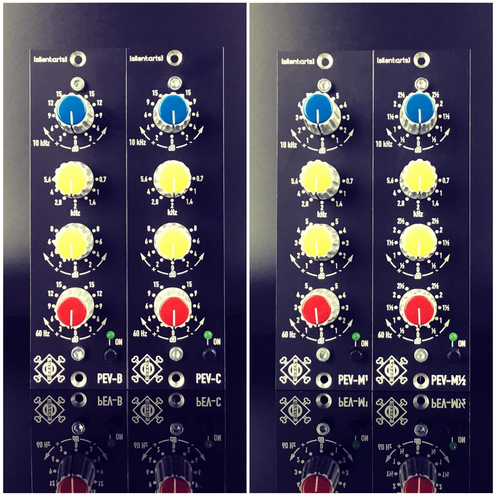
While looking on the Neumann PEVc schematic floating around the web I always thought this would be a cool project for a 500 series module. We found that there were several different versions of this EQ, some with 4 discrete op amps (Neumann OA10), some with 5 discrete op amps, and there was also a PEVb with different gain steps.
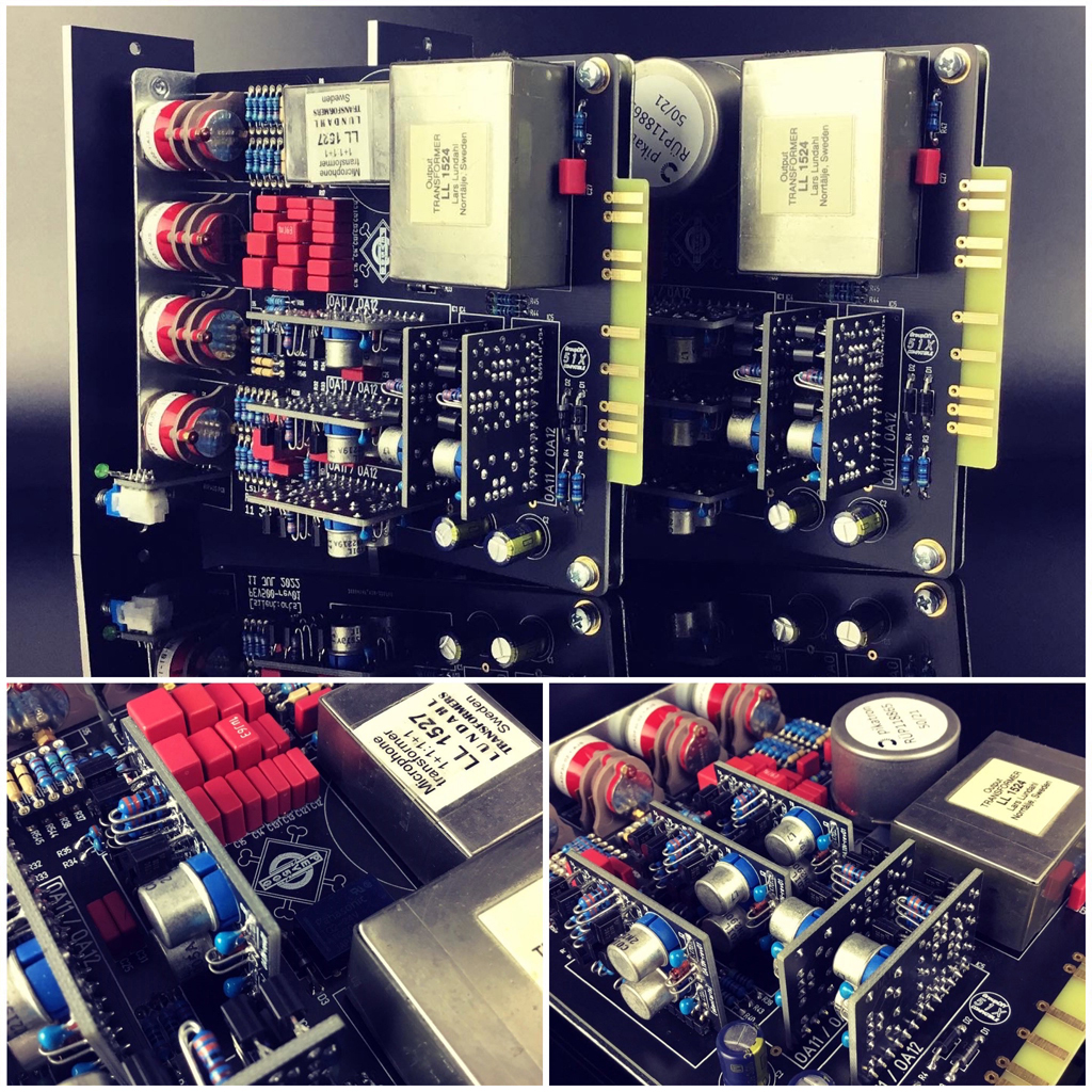
For our PEV500 we decided to go with five OA11N op amps, our own mixture of the Neumann OA10 and OA12 using 10 transistors each. Gain steps are either original PEVb, PEVc, 1 dB steps only (PEV-M1), or 0,5 dB steps (PEV-M2).
PEV500 Schematic
PEV500 PCBs
PEV500 Parts List
PEV-B Resistors
PEV-C Resistors
PEV-M1 Resistors
PEV-M2 Resistors
OA11N
#PEV500 on Instagram

