wow --- i'm beaming with pride... :green:
You are using an out of date browser. It may not display this or other websites correctly.
You should upgrade or use an alternative browser.
You should upgrade or use an alternative browser.
PGA2500
- Thread starter Rochey
- Start date


Help Support GroupDIY Audio Forum:
This site may earn a commission from merchant affiliate
links, including eBay, Amazon, and others.
jdbakker
Well-known member
Just FYI, I have a board design for the PGA2500 in the Portable HDD Recorder thread. Schematics are here and here, the parts placement is here. All parts are available from Digi-Key.
JDB.
[hit a few speedbumps. PCBs are in production now; scheduled to get shipped back to me coming Thursday]
JDB.
[hit a few speedbumps. PCBs are in production now; scheduled to get shipped back to me coming Thursday]
Mac*ie TT24 I presume ?But last week I had access to a product based on this chip.
chrissugar
Well-known member
[quote author="jdbakker"]Just FYI, I have a board design for the PGA2500 in the Portable HDD Recorder thread. Schematics are here and here, the parts placement is here. All parts are available from Digi-Key.
[/quote]
hey JDB
I can't find the part of the circuit that I was looking for, the digital control.
[quote author="Gulistan"]
Come on. Since when is the M company a top of the line company? :?
I'm talking about a company of the level of Cranesong, PrismSound, Maselec, EAR etc. :grin:
Interesting is that it is not only my impression that this is a very clean preamp, there are many classical music recordists that think it is excellent. I just never knew it uses this chip.
chrissugar
[/quote]
hey JDB
I can't find the part of the circuit that I was looking for, the digital control.
[quote author="Gulistan"]
Mac*ie TT24 I presume ?[/quote]But last week I had access to a product based on this chip.
Come on. Since when is the M company a top of the line company? :?
I'm talking about a company of the level of Cranesong, PrismSound, Maselec, EAR etc. :grin:
Interesting is that it is not only my impression that this is a very clean preamp, there are many classical music recordists that think it is excellent. I just never knew it uses this chip.
chrissugar
jdbakker
Well-known member
[quote author="chrissugar"][quote author="jdbakker"]Just FYI, I have a board design for the PGA2500 in the Portable HDD Recorder thread. Schematics are here and here, the parts placement is here. All parts are available from Digi-Key.
[/quote]
hey JDB
I can't find the part of the circuit that I was looking for, the digital control.[/quote]
Ah, I see. Well, that must be because I haven't published it yet, which is mostly because it isn't done yet {insert sheepish grin emoticon}. As mentioned in the recorder thread I simply use three output lines on an AVR microcontroller (chip select, clock, data). I don't bother with the Data Out pin on the PGA2500, as I don't daisy chain the parts. So really the gain control is more software than schematics.
Do you have any specific bits you'd like to discuss (discrete vs microcontroller, which microcontroller, strategies to keep the coupled noise down) ?
JDB.
Assuming that you don't need a fast processor just to control values like this. In which case, I would think that running a small micro off the ADC system clock would work quite well.
I know this kind of thing is done with switching power supplies, where the power supply is switched at a rate that is a multiple of the sampling frequency and synchronised as well.
I guess my question is: would running a small micro (like an MSP430) from 256fS clock make sure that any "noise" generated would actually be synch'd with the ADC, and then somehow... cancel out?
jdbakker
Well-known member
[quote author="Rochey"]I know this kind of thing is done with switching power supplies, where the power supply is switched at a rate that is a multiple of the sampling frequency and synchronised as well.[/quote]
Yes, that works well, especially if the switcher runs at a submultiple (divisor?) of the sigma/delta modulator. I use this technique in my HDD recorder.
[quote author="Rochey"]I guess my question is: would running a small micro (like an MSP430) from 256fS clock make sure that any "noise" generated would actually be synch'd with the ADC, and then somehow... cancel out?[/quote]
Not necessarily. As you pointed out in another thread, perfectly synchronous digital signals can still produce noise in an ADC. In a previous life I did CPU power measurements on low-power systems; you could see periodic tasks like the timer interrupt clearly reflected in the system's power consumption. Think PC near AM radio: for that kind of hash it doesn't matter much if you're sync or not.
If you can't shield or create distance between analog and digital, there are two ways to reduce the impact of the interference: make sure all periodical emissions are above Fs (or more precisely: in the stop band of the ADC's oversampling filter), or make all emissions aperiodical enough that they look like white noise. Neither is trivial.
JDB.
[putting your CPU to sleep when it's not used helps too, like Joe says upthread]
I'm thinking of doing that for an MSP430 controller for the ADC's and PGA2500.
An MSP430 can sit in a low power mode until a rotary encoder triggers an interrupt and runs the routine to update the gain
i think THAT's how JLM did it")
An MSP430 can sit in a low power mode until a rotary encoder triggers an interrupt and runs the routine to update the gain
i think THAT's how JLM did it
JLM Audio
Well-known member
Yes that is right.i think THAT's how JLM did it
We could easily change the programing in the new tiny CPU PCB from our HAL project to control a PGA2500 instead of the PGA2320 and show level with the display PCB but would need make a new PGA2500 PCB. The only thing I don't like about the PGA2500 is that fact it's audio only runs on +/-5v. If there was a version that ran on +/-15v like the PGA2320 it would make the smallest clean pro mic pre.
CPU PCB (1.38" x 2") + STEREO VOLUME CONTROL PCB (1.38"x 2") + DISPLAY PCB (1.38" x 2.8")
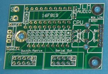
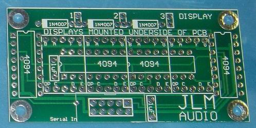

More info on the HAL project here
http://jlmaudio.com/index.php?topic=3#3
chrissugar
Well-known member
[quote author="jdbakker"]Do you have any specific bits you'd like to discuss (discrete vs microcontroller, which microcontroller, strategies to keep the coupled noise down)[/quote]
I'm for discrete, anything microcontroller scare the hell out of me :grin:
[quote author="JLM Audio"] The only thing I don't like about the PGA2500 is that fact it's audio only runs on +/-5v. [/quote]
In the product I'm talking about this is solved very simple. The output stage is also the PAD circuit. When the preamp is in the low gain region the two output opamps behaves like a simple GAIN=1 noninverting buffer. When the high gain is activated, a relay configure the two output buffer opamps in 10dB gain mode. In this mode it can put out enough voltage to drive any AD to full scale.
I forgot to mention that square wave behaviour is excellent, no ripple, no nothing.
chrissugar
recnsci
Well-known member
[quote author="chrissugar"]
I'm for discrete, anything microcontroller scare the hell out of me :grin:
[/quote]
Don't be scared. MCU will be, by wide margin, better solution here,
in case that this turns into group project.
[quote author="JLM Audio"] The only thing I don't like about the PGA2500 is that fact it's audio only runs on +/-5v. [/quote]
Corect me if I'm wrong, but IIRC API 312 has around 10dB of transformer
gain, right? In that case, PGA2500 on +-5V will have same headroom as
API312 on +-15 supply, if you look from the mic.
That is , if headroom is your reason for concerne. Pad will be
needed on hot signals anyway.
IMHO bigger issue is gap between 0 and 10db.
cheerz
urosh
[quote author="JLM Audio"]
[/quote]
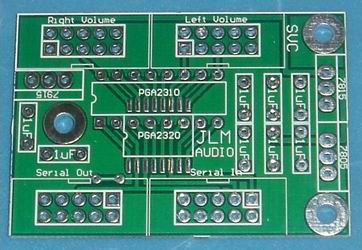
I love the dual layout for PGA2310 and PGA2320...
I love the dual layout for PGA2310 and PGA2320...
chrissugar
Well-known member
Just a little bump.
I'm stil shocked how transparent this PGA2500 based preamp can sound. I would really like to build some channels. Anyone have some progress with a digital gain control solution? :grin:
chrissugar
I'm stil shocked how transparent this PGA2500 based preamp can sound. I would really like to build some channels. Anyone have some progress with a digital gain control solution? :grin:
chrissugar
http://www.msp430.com
MSP430F2003
we already have code that will read a voltage from the ADC to create a value.
There is also code for 16bit SPI.
A little microcontroller knowledge (which I had, but lost over time) to combine both (it's a total of less than 100 lines of code) and you have a system that reads the voltage input and converts it into SPI code.
Sweet
MSP430F2003
we already have code that will read a voltage from the ADC to create a value.
Code:
#include  <msp430x20x3.h>

void main(void)
{
  WDTCTL = WDTPW + WDTHOLD;                 // Stop watchdog timer
  P1DIR |= 0x01;                            // Set P1.0 to output direction
  SD16CTL = SD16REFON + SD16SSEL_1;         // 1.2V ref, SMCLK
  SD16INCTL0 = SD16INCH_1;                  // A1+/-
  SD16CCTL0 =  SD16UNI + SD16IE;            // 256OSR, unipolar, interrupt enable
  SD16AE = SD16AE2;                         // P1.1 A1+, A1- = VSS
  SD16CCTL0 |= SD16SC;                      // Set bit to start conversion

  _BIS_SR(LPM0_bits + GIE);
}

#pragma vector = SD16_VECTOR
__interrupt void SD16ISR(void)
{
  if (SD16MEM0 < 0x7FFF)           	    // SD16MEM0 > 0.3V?, clears IFG
    P1OUT &= ~0x01;
  else
    P1OUT |= 0x01;
}
There is also code for 16bit SPI.
Code:
#include <msp430x20x3.h>

void main(void)
{
  volatile unsigned int i;

  WDTCTL = WDTPW + WDTHOLD;             // Stop watchdog timer
  P1OUT =  0x10;                        // P1.4 set, else reset
  P1REN |= 0x10;                        // P1.4 pullup
  P1DIR = 0x01;                         // P1.0 output, else input
  USICTL0 |= USIPE7 +  USIPE6 + USIPE5 + USIMST + USIOE; // Port, SPI master
  USICTL1 |= USIIE;                     // Counter interrupt, flag remains set
  USICKCTL = USIDIV_4 + USISSEL_2;      // /16 SMCLK
  USICTL0 &= ~USISWRST;                 // USI released for operation
  USISRL = P1IN;                        // init-load data

  P1DIR |= 0x04;                        // Reset Slave
  P1DIR &= ~0x04;
  for (i = 0xFFF; i > 0; i--);          // Time for slave to ready
  USICNT = 8;                           // init-load counter
  _BIS_SR(LPM0_bits + GIE);             // Enter LPM0 w/ interrupt
}

// USI interrupt service routine
#pragma vector=USI_VECTOR
__interrupt void universal_serial_interface(void)
{
  if (0x10 & USISRL)
    P1OUT |= 0x01;
  else
    P1OUT &= ~0x01;
  USISRL = P1IN;
  USICNT = 8;                           // re-load counter
}
A little microcontroller knowledge (which I had, but lost over time) to combine both (it's a total of less than 100 lines of code) and you have a system that reads the voltage input and converts it into SPI code.
Sweet
The PSuedo-code for this is relatively simple...
- Set up the device I/O's
- 10 times per second (based on an interrupt):
- Read-in ADC Value
- Map ADC value to gain levels.
- Write gain level to register.
- Compare new value to previous value.
- If there is a difference, call SPI function with the new value.
I shall add -- if someone is genuinly capable of doing this, I will donate an MSP430 USB Dev Kit (http://www.ti-estore.com/merchant2/merchant.mvc?Screen=PROD&Product_Code=EZ430-F2013) to them. They will also recieve a finished board that will contain the msp430 and PGA2500.
SSLtech
Well-known member
Rochey, can you put this together into project form? -If so, I've a feeling this could be kitted, and you could do the PCBs for the honey-fund...
Even your overlords at Tejas Strumenti would probably be amused...
I'll design the PSU.
Keef
Even your overlords at Tejas Strumenti would probably be amused...
I'll design the PSU.
Keef
Keef,
Awsome idea.
I'm in for the layout and schematic capture if you can do the power side.
I also have a mic front end for the device pretty much done.
Just need someone to do the software.
Awsome idea.
I'm in for the layout and schematic capture if you can do the power side.
I also have a mic front end for the device pretty much done.
Just need someone to do the software.
SSLtech
Well-known member
Rochey,
You know what I'm involved in project-wise, and sets of these with mapped/matched gain would be VERY important... -I could possibly even sell a couple before you know it, to a couple of other like-minded hobbyists!
Hell, it would likely beat the pants off of the other stuff that I built recently!
Keith
jdbakker
Well-known member
[quote author="Rochey"]
- 10 times per second (based on an interrupt):
- Read-in ADC Value
- Map ADC value to gain levels.
- Write gain level to register.
- Compare new value to previous value.
- If there is a difference, call SPI function with the new value.[/quote]
While that works, it's a bit noisy. What I would do is add a window comparator plus an external R2R DAC/digital potmeter. This changes the procedure to:
[quote author="Rochey"]I shall add -- if someone is genuinly capable of doing this, I will donate an MSP430 USB Dev Kit (http://www.ti-estore.com/merchant2/merchant.mvc?Screen=PROD&Product_Code=EZ430-F2013) to them. They will also recieve a finished board that will contain the msp430 and PGA2500.[/quote]
I'm game if noone else is. I'm still waiting for some of the parts for my HDD recorder, and I'll need similar code anyway.
JDB.
[Xilinx CPLDs: gotta love parts which go from 'in stock' to 'three months lead time' overnight]
- 10 times per second (based on an interrupt):
- Read-in ADC Value
- Map ADC value to gain levels.
- Write gain level to register.
- Compare new value to previous value.
- If there is a difference, call SPI function with the new value.[/quote]
While that works, it's a bit noisy. What I would do is add a window comparator plus an external R2R DAC/digital potmeter. This changes the procedure to:
- * wait for the window comparator to wake the CPU
* read ADC
* write new gain level to PGA2500
* set DAC to re-center window comparator
* put CPU to sleep
[quote author="Rochey"]I shall add -- if someone is genuinly capable of doing this, I will donate an MSP430 USB Dev Kit (http://www.ti-estore.com/merchant2/merchant.mvc?Screen=PROD&Product_Code=EZ430-F2013) to them. They will also recieve a finished board that will contain the msp430 and PGA2500.[/quote]
I'm game if noone else is. I'm still waiting for some of the parts for my HDD recorder, and I'll need similar code anyway.
JDB.
[Xilinx CPLDs: gotta love parts which go from 'in stock' to 'three months lead time' overnight]
JD,
check your pm.
BTW - don't you have a PGA2500 EVM?
check your pm.
BTW - don't you have a PGA2500 EVM?
Similar threads
- Replies
- 0
- Views
- 1K
- Replies
- 17
- Views
- 6K
- Replies
- 10
- Views
- 4K
- Replies
- 1
- Views
- 1K