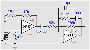
> MM cartridge loading, like resistance and capacitance (including cables), matters for top octave frequency response.
Sure. In ~~1954 a cart needed significant inductance to lever-up output above vacuum-tube noise. Also the tube was usually 3 feet away, so you had significant capacitance, both cable and tube.
For a while, each needle-winder specified different R and C loading.
The upshot was some agreement on 47K. C was not specified, but was pretty sure to be over 100pFd yet rarely over 300pFd.
Figure 200pFd and 600mH. 14.5KHz. Figure Q: 600mH at 14.5KHz is 54K8, loaded in 47K is Q=0.86. The electrical L-C-R -3dB point will be near 18KHz, which is pretty good for 1950s hi-fi. Changing to 150pFd or 250pFd has little effect below 15KHz, because the 47K tends to even things out. Omit the 47K and you get a hi-Q ring at 14.5KHz. Actually what they did was match the R to the reactance of the typical C at the high end of the audio band. The needle-maker may select L over a wide range: higher because that gives more output or less magnet-mass, lower to push the resonance toward 20KC, or balance resonance against mechanical losses in the upper octave.
There are mavricks. Grado carts had very low L, the resonance was way-high, loading was nearly unimportant. Some others are quite fussy.
Assuming a damped resonance at the top of the band is not unusual in audio.
Cowles proposes a very different plan. Hang a heavy load on the inductance. Cart output droops above 2KHz (you hope and trim). "Free" RIAA pole! The expected resonance in the last octave is heavily damped, Q=0.16. Large change in C does not matter because this is hardly a resonance at all. If you assume 100pFd (3 feet) cable, this matches the 7.5K load at 200KHz! Your electrical response is "flat" (relative to RIAA) a decade past the audio band, no 12dB/oct above 15-20KHz as with 600mH 200pFd 47K loading. You DO lose any bump-trick the cart designer expected to get by trimming L against 47K and typical C.
RIAA Noise is a complicated thing, National published a paper once, and I'm not up to running the calcs with this different plan. But note that while this "has 15K excess resistance", the normal plan is ~~5K below 2KHz rising to 47K at top resonance.
> Wonder how would a mpsa18 work..)
Read the paper. "At 30Hz the gain is determined by the transistor current gain... at least 60." Or, assuming all the caps let-go at 30Hz, you have 15K into the base and 10K load. If Hfe is unity, gain is 10K/15K= 0.67, if Hfe were 100 then gain is 100*10K/15K= 67.
Ah, I see the inevitable flaw. 1KHz gain is nearly 150K/15K= 10. We usually want 1KHz gain to be 50 or 100.
MPSA18 is Hfe 500 or more. 30Hz gain seems to be over 300, maybe 1000! WAY too high for 1KHz gain of 10! RIAA is asymtotic to a 10:1 rise each half of the audio band.
Ah... Now scale the 150K to like 1Meg, midband gain near 50, and a reasonable rise to 30Hz. C1 must go down to 290pFd. The 1M5+1M5 bias chain also scales with Hfe, should total like 5M or 10Meg, and the 0.03u may change. Although, you could replace the T with a single 1.5Meg, hang 100K base to ground to get DC operating point (you love your DC) on a good zone.
If you have a Grado, the C2 has to be near 100pFd, and may fuss-at transistor capacitance. We know the Grado did not need L-R-C resonance to tweak its top octave so you are not losing that design-trick.
It might be "better" with that hi-gain transistor.


