Power supply Q's

GroupDIY Audio Forum

Help Support GroupDIY Audio Forum:

This site may earn a commission from merchant affiliate links, including eBay, Amazon, and others.

Rochey

Well-known member
White Market Member
Joined
Jul 2, 2004
Messages
2,699
Location
Dallas, TX - Formerly UK
Heya guys, I'm trying (and trying very hard, i'm useless as design of anything that's not in a datasheet :sad: ) to modify SSLtech's power supply and add a +5V rail as well (for some digital logic stuff)

The +5V is also driving some 5V relay's, so I need a fair bit of juice. The design below is using two 7805's to provide 2A of available current.

powersupplytocheck.jpg


This design is by no way finished, what i'm really looking for is a sanity check :sad: If you guys spot any components that are uneeded or are the wrong value, or even things which are missing, i'd really appreciate it if you could point the problems out.

Yo Ho Ho, Merry Christmas and thanks again,

Rochey
 
well, the relay's I've seen have about 100 Ohms each at 5Volts.

Using my crappy electronics knowledge (V=IR) i get 5/100 = 0.05Amps

Now, my mic front ends (based on peter purposes' card) have 3 relays each - multiplied by 8 cards in a system = (24 relays at peak). Add some logic and processing ( :grin: )

I have another week and a bit to get some more design done - then it's back to work :sad:

Cheers

R
 
> what i'm really looking for is a sanity check

You can NOT parallel 7805 regulators to double the output current. Their "5V" will really be 5.05V on one, 4.95V on the other, something like that, NOT matched. So the higher-volt one will take all the load until it over-heats, shuts-down. Then the other one will take the load, over-heat, shut-down.

There is a 3A 5V regulator, look in your company or competitors' databooks.

However I also think it is insane to expect three different rails covering 10:1 of voltage, lowest voltage being VERY high current, all from one transformer. And mixing audio and logic is a bad idea.

Get a real 5V supply JUST for the logic. And one good source is the wall-wart from a discarded USB-1 hub. All the wart-power USB hubs I've seen use a 5V 2A wart. I realize you don't want a wart hanging off your system, so mount a "wall" socket inside the case.

> The +5V is also driving some 5V relays, so I need a fair bit of juice. The design below is using two 7805s to provide 2A of available current.

Can't you use 5V logic with high voltage buffers to drive 24V relays? 1.2A of "clack" will leak into your audio; 24V relays will use 1/5th the current, less clack. If your logic is a watt or so, it isn't a big waste to drop that off an 18V rail.

Also: don't these 780x/790x regulators want more output capacitance than you have shown?

Small detail: I agree you could need zero to eight Pad and Phantom at once, but you won't normally ever have ALL your Phase relays energized. If all your mikes are properly phased, you rarely need the Phase function. If mikes are randomly phased and random distances from narrow-band phase-critical instruments, on average half your Phase need flipping. If you find 1 Norm and 7 Reversed, you can invert the problem to 1 Reversed and 7 Norm. So a more likely worst-case might be 20 relays ON at once. I agree that 20 or 24 is about the same power problem. Also that idea fails if you are sensitive to Absolute Phase, but in that case you shouldn't be working with randomly phased mikes and mike locations. ANd personally I suspect absolute phase matters only for large struck drums; all other music phase is relative phase. And there is no absolute phase through the mass-market chain: while conventions are clear, it takes just one inversion in the duplication or in the playback system to make a mockery of Absolute Phase.
 
PRR --

thanks a million, there's a lot to think about there, which in my current state on Christmas day, i'm not in a position to think it completely through. My initial scan through it looks good, I agree about the transformer and the outputs required, as well as the parallelling (sp) of the 7805's.

I think it's time to go back to the drawing board a little and tweak :D

I'll have a look into some high voltage buffers to go from 5v to 24V. At the moment, all I could find was 5v in 5v.

Anyway, dinner is on the table,

Merry Christmas Folks,

R
 
[quote author="PRR"]
However I also think it is insane to expect three different rails covering 10:1 of voltage, lowest voltage being VERY high current, all from one transformer. And mixing audio and logic is a bad idea.
[/quote]

PRR - this will seem a stupid question, but...

If all i'm pulling off the transformer is -+20V and GND, then whats the problem running them to rectifiers and different regulators? I would have thought that as long as the transformer can handle the power throughput, it'd be okay.

So, with a small design change - I now have the rails of:

+5V for digital logic (which may be regulated down nearer any processor) -- digital
+12V for relay switching -- digital? (and maybe some display driving)
-+15V (or 18... depends on my opamps etc) -- analogue


Finally, I know that Audio and logic power should be kept apart, but surely they can come from the same transformer outputs. Aren't they 'separate' once they are independantly regulated?

Okay, enough of my showing my lack of knowledge :grin: Merry Christmas folks..

R
 
you can keep them from the same transformer but you also have to realize that digital(i say digital because it's off or on like a relay) switching causes the ground to move up/down slightlyi potential. It's usually called digital bounce/ground bounce. this can cause some vregs to be unstable, it is also creating noise on ground. This is the reason most devices keep analog and digital ground separate. If you *have* to use the same ground point, at least separate them completely except for one point, but at that point cut the two grounds apart and place a high value ferrite bead between them. this should keep the potentials similar enough but keep noise from getting through. usually this is done under DACs and ADCs where the two grounds would meet. also, Your centertap is assumed to be your Ground reference.. hmm something seems strange about how you have your recifier setup for the 7805s.. the negative side of your bridge is floating on your schematic. did you mean to leave it like that?

PRR is right about paralleling Vregs. they don't like it. What relays are you using and how many? 2A is a lot to ask at 5v.. so switching via FETs/FETdrivers at higher voltages is a better idea. try the TC427 or TC4427 drivers. very straight forward and simple.
 
[quote author="Svart"]hmm something seems strange about how you have your recifier setup for the 7805s.. the negative side of your bridge is floating on your schematic. did you mean to leave it like that?[/quote]

I figured that i didn't need a negative output from it to generate the +5V. I didn't really know what to do with it from there!

Maybe tie it to ground with a resistor?

I've decided to keep the grounds separate for each circuit - and bring both grounds (digital and analogue) back separately on each cards power connector to the power supply.

Sound nuts?
 
> your recifier setup for the 7805s.. the negative side of your bridge is floating on your schematic. did you mean to leave it like that?

Odd but perfectly OK. The lowest-parts answer is: use two plain rectifiers instead of half a bridge rectifier. But actually it is less wiring and about the same price or cheaper to buy a 10-bag of bridges and use half-a-bridge for unipolar outputs.

> I know that Audio and logic power should be kept apart, but surely they can come from the same transformer outputs. Aren't they 'separate' once they are independantly regulated?

No, for reasons Svart explained well. The "regulators" reference a "ground" that has thundering ground-spikes in it.

> I would have thought that as long as the transformer can handle the power throughput, it'd be okay.

That transformer has to be rated for the highest voltage in the system, say 56V (+/-18V after regulation) and the sum of all the currents. Your +/-18V supply is maybe 400mA? And your +5V is 2A, or 1A per side. AC current will be about twice DC current. So you need 40 VAC and 2 Amps AC, an 80VA core. Only 24.5 Watts does useful work (opamps or relays). There is an AWFUL lot of waste heat.

Powering 5V 2A from 20VAC, you have a raw DC supply of 20VAC*1.414= 28V. 5V ends up in logic and relays, 28V-5V= 23V in the regulator. 23V*2A= 46 Watts of wasted heat in the 5V regulator!

From a thermal point of view, the 5V regulator needs a heatsink like from a 100 Watt amplifier.

Economically, that 46 Watts of waste heat costs about a penny an hour on the electric bill. True, if you rent the studio for $100/hr this is small potatoes. But as a personal toy, it costs about $1/month to run, so in a year or two its electric-cost would pay-off the price of a 12VAC CT 2A 24VA transformer, which would waste a lot less power (5V is always wasteful), eat less, and need less regulator heatsinking. And also float the logic ground so it isn't dumping through the analog ground.

(If you are lucky, you can find some surplus tranny with 40VCT plus 12VCT windings, which will work.)

> If I drive my relays with http://focus.ti.com/lit/ds/symlink/sn754410.pdf then i can feed it some basic +5V and feed the relays with a far higher voltage at a lower current.

What are you, a chip-salesman???? (Oh, that's right, you are.....)

That chip is way overkill. I'd do it with one transistor, one resistor, and one diode. Some younger guys will tell you to use a MOSFET, no resistor, maybe no diode. And there are chips to combine all this at maybe less cost/work than discrete solutions.

Use the 2001-2003 chips. They are probably older than you are, and I had some run-around figuring out what prefixes are used now: ULN2001 ULQ2003 DS2003 But here's one you can get from TI: http://www-s.ti.com/sc/ds/ulq2003a.pdf "high-voltage, high-current Darlington transistor arrays. Each consists of seven npn Darlington pairs that feature high-voltage outputs with common-cathode clamp diodes for switching inductive loads. The collector-current rating of a single Darlington pair is 500 mA."

You may not need 7 drivers in one place, but the price is only a buck each (a lot less if you hunt surplus: 2003s have been made and surplused by the millions for over 30 years). That sn754410 costs a whopping $2, and has a lot of frivolous functions and pins to defeat or strap.

> Sound nuts?

Yes, we are.
 
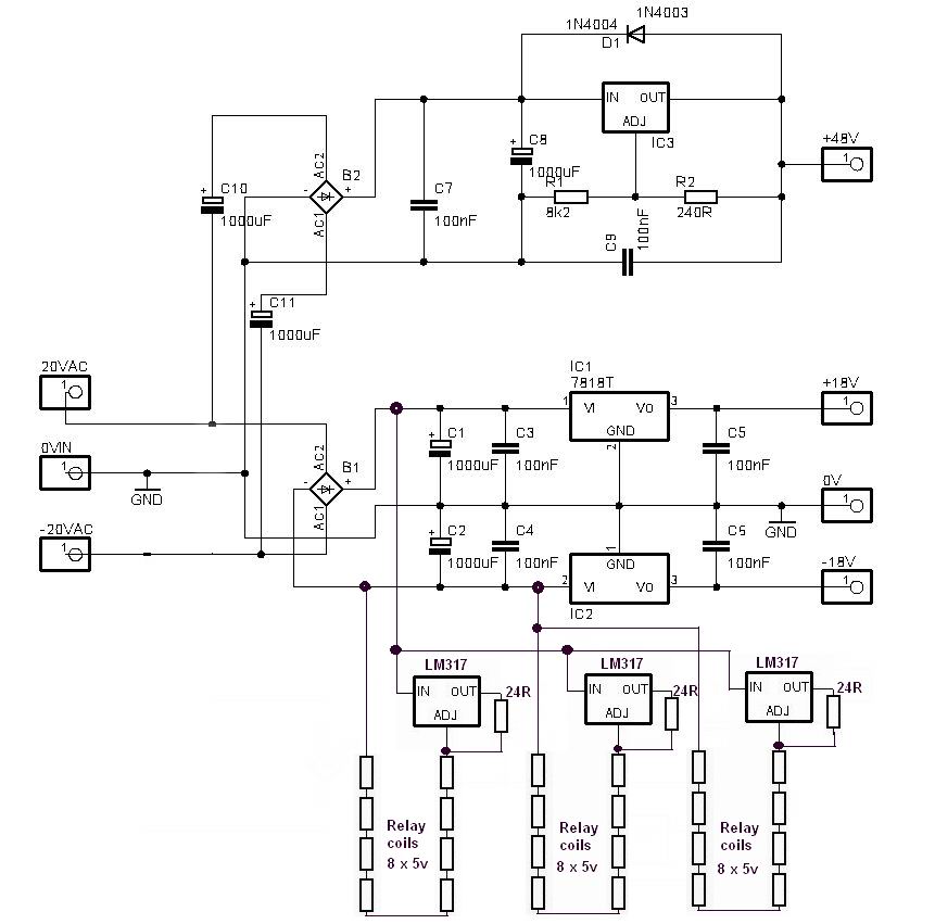
Using a constant current source for each string of 8 relays running from the unregulated +/-28vdc rails would make electrically quiet relay switching. Also the constant 150mA load across the +/-28v rails would only use a constant 8.4Watts of power which is only 2.8Watts across each LM317 reg with all relay coils shorted out by there on/off switches.
powersupplymod.jpg


Check out this PDF link below on the JLM web site to see the full idea at work.

http://www.jlmaudio.com/JLM99XMB.pdf
http://www.jlmaudio.com/JLM99V.htm

Also C1 & C2 should be at least 2200uF or more and C5, C6 should have 10uF across them as well for the 78/79 reg series. If you did want to go with a 5v rail you should use a seperate low voltage winding to minimise wasted heat in the 5v reg. Also if you went that way you could use the ULN2803 which the 8 way pack version of the ULN2003. If using the ULN devices it is best to set the 5v rail to 5.6v to make up for the lost 0.6volt across the output transistor in the ULN device to insure proper relay operation.

Joe
 
Good input JLM and PRR!

I'm a young guy and I'd say to stick a MOSFET in there! most MOSFETS can be purchased with the flywheel diode build right on the die eliminating the need for external diodes.. guess i'm just new fashioned.. :green:
 
[quote author="JLM Audio"] If you did want to go with a 5v rail you should use a seperate low voltage winding to minimise wasted heat in the 5v reg. Joe[/quote]

Joe & PRR -- thanks for reminding me about this one. I forgot that i've got to dissipate 15Volts of about 2A if I go with the 2A requirement of the 5V regulators... That's one mighty heatsink.

having scratched my head and slapped my forehead a few times having remembered some of the things from many years ago, I think PRR is right in suggesting the 2003 device. I'll drive it from a 5V CMOS input and then use a 12V power rail to switch the relays (as mentioned earlier). Using 12V lowers the current requirement for the 12V rail as well.

I figure a separate power rail for the actual switching will keep teh system pretty clean.

To go back to the noisy earth problem (with the analogue circuitry and the digital circuitry) could I simply use 2 different transformers? One to generate the digital voltages (including the relay switch) and another for any analogue opamps etc that i'm working with.

Once again, sound nuts?

Thanks again,

R
 
heya folks --

i'm a little further ahead with my plans for world domination. I've split my power supply into 2 - a digital PS and an Analogue PS. The split is because different project I'm dreaming of may not need the digital power supply etc.

Anyway, my analog power supply is basically a mirror image of Keiths one - that'll provide -15V +15V and 48V from a 20V-0-20V transformer.

The digital one is where I have more questions. The relays I'm planning to use in my system are now 12V relays (so I can bring the current down). The other rails I need from the digital supply are +5 and -5V. Those rails are very low current, as they are powering basic logic and maybe a small micro - nothing to worry about.


So, without further ado, here's my very basic digital supply - i kinda took what Keith had done and changed it for my own needs. The only thing i wasn't sure about was capacitor values etc. From what I can see (and understand) those capacitors are there to store charge just in case there are any large current surges (such as switching etc)?


digitalpowersupply.GIF


Please give me some feedback, so I can feel confident enough to go to layout on this one.

Thanks again,

R
 

Latest posts

Back
Top