Pultec combo - MEQ5 + EQP1A

GroupDIY Audio Forum

Help Support GroupDIY Audio Forum:

This site may earn a commission from merchant affiliate links, including eBay, Amazon, and others.

saint gillis

Well-known member
Joined
Nov 4, 2012
Messages
915
Location
Brussels - Belgium
Hello, I've made a combo Pultec with an MEQ5 and a EQP1A in the same 2U 19'' rack :
pannel.jpg


We can choose to use only one of each or booth at the same time, there is only one input and one output, the idea was to save space and being able to use these 2 wonderful eqs at the same time in the same circuit, thus saving 2 transformers

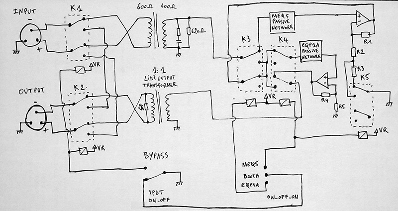
Of course it was difficult to use tube amplifiers because of space so I choose 990C op amps, here is the block diagram :
block%20diagram.jpg


Never more than 2 relays at the same time, so very low power consumption, there is a trick to stay everytime in unity gain (because of transformer loss etc).

Here is the corrected schematic of the MEQ5 passive network, I verified all the curves with RMAA, looks great (and sounds great), thanks one more time to Gyraf for the ressources he offers to us! :
meq5_reference_new_ok.jpg


On the block diagram, R2 & R5 are in fact a resistor + a trimmer to adjust unity gain, R3 is another trimmer... I used DC servos to remove dc from the op amps outputs and kind of JT-OLI-2 at the output of each op amp, and on grounded side of the output transformer, just like on Jensen's schematics.
I used Sowter 5069 on input and Lundahl 2811 on output which showed a little bit of distortion on square waves (because of its little size I guess) but I m very satisfied with the sound and the linearity is quite perfect. The inductors come from Don Audio in Germany (thanks to Aaron, great guy).

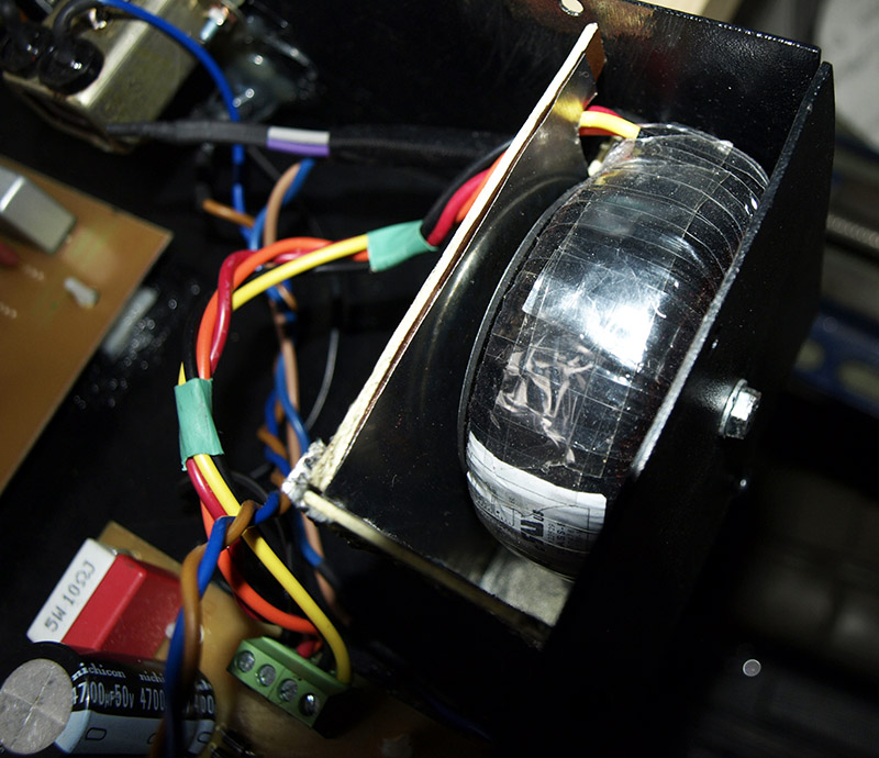
  When testing the unit, it was a bit noisy when boosting high frequencies on the MEQ5, it came from the PSU toroidal transformer, but finding the right place for it was the solution (right back corner of the rack) , and adding a sheet of mu-metal made the unit perfectly silent any frequency at full boost :
transfo.jpg


I don't share pcbs because I used a kind of custom DOA footprint, but the block diagram tells everything...

It is amazing to see that a design from 1951 (maybe even before) remains so terrific! These 2 eqs together are simply the best
 
Great!!!

I've been wandering about this project for a long time, after reading related threads and reading your schematic i just realized that the key is putting MEQ before EQP1A and adding some resistors and a trimmer for unity gain?

Did you calculate total loss (and gain) in dB's at the input/output?
 
Yes in theory (simulation) it gave me if I remember well around -26db of loss for the MEQ5 and around -22db for the EQP1A passive network, +1 or 2db with the transformers.. I have to mention that afterwards I added a 10k load at the end of the EQP1A passive circuit.
In real life, the MEQ5 produced a loss of around -30db, the EQP1A -28/-29db and transformers' insertion loss was -1,5db .

I used 10k for R1/R4, 330R + 100R trimmer for R5, 220R + 100R trimmer for R2, and if I remember well I calculated a 200R trimmer for R3 for top comfort biasing but I put a 500R and it is totally fine...
 
We began to use it in the studio for vocals, bass, drums & guitars, I must say that it is always in the "booth" position, but you know what it is when you get a new device, you can make mistakes..
 
I ve asked on gearslutz for the pluging order, "harrypurser" told me to put the MEQ5 before because "anything with a high frequency boost should come first, so you don't pull up noise from any previous unit in the chain".. makes sense..
 
saint gillis said:
Hello, I've made a combo Pultec with an MEQ5 and a EQP1A in the same 2U 19'' rack :
pannel.jpg


We can choose to use only one of each or booth at the same time, there is only one input and one output, the idea was to save space and being able to use these 2 wonderful eqs at the same time in the same circuit, thus saving 2 transformers

Of course it was difficult to use tube amplifiers because of space so I choose 990C op amps, here is the block diagram :
block%20diagram.jpg


Never more than 2 relays at the same time, so very low power consumption, there is a trick to stay everytime in unity gain (because of transformer loss etc).

Here is the corrected schematic of the MEQ5 passive network, I verified all the curves with RMAA, looks great (and sounds great), thanks one more time to Gyraf for the ressources he offers to us! :
meq5_reference_new_ok.jpg


On the block diagram, R2 & R5 are in fact a resistor + a trimmer to adjust unity gain, R3 is another trimmer... I used DC servos to remove dc from the op amps outputs and kind of JT-OLI-2 at the output of each op amp, and on grounded side of the output transformer, just like on Jensen's schematics.
I used Sowter 5069 on input and Lundahl 2811 on output which showed a little bit of distortion on square waves (because of its little size I guess) but I m very satisfied with the sound and the linearity is quite perfect. The inductors come from Don Audio in Germany (thanks to Aaron, great guy).

  When testing the unit, it was a bit noisy when boosting high frequencies on the MEQ5, it came from the PSU toroidal transformer, but finding the right place for it was the solution (right back corner of the rack) , and adding a sheet of mu-metal made the unit perfectly silent any frequency at full boost :
transfo.jpg


I don't share pcbs because I used a kind of custom DOA footprint, but the block diagram tells everything...

It is amazing to see that a design from 1951 (maybe even before) remains so terrific! These 2 eqs together are simply the best

I recently finnished an MEQ-5 build based on the Gyraf Schem  - I still need to buy new caps because I used the original values - would you say yours are more accurate than the attached correction I have?
 

Attachments

  • meq5_updated_2008.jpg
    meq5_updated_2008.jpg
    87.5 KB
saint gillis said:
Hi!
Sorry I haven't been connected since a while..
Yes it is, but I have to post an update, I'll do it asap..

No problem - I see you were also a part of this thread some time ago http://groupdiy.com/index.php?topic=27624.0

I used the calculator at http://www.pronine.ca/lcf.htm in conjuction with the "updated values" in 2008 posted in the thread and your values posted in this thread alongside the panel values and the combinations of caps that were available. Attached was my result;

Mine were the same as yours in most places, the only differences I found were in the low boost section.

I am also not sure what is being indicated in the MEQ5_Updates_2008 image I posted previously with the Hi Boost (3khz) 477mH and (2khz) 625mH have red dots and lines?


Attachments

  • MEQ5 Cap Value Changes.PNG
    MEQ5 Cap Value Changes.PNG
    22.4 KB
Hi!
Here is what I used (file above updated)

  Indeed the low boost values are not exactly the written value but something like ~ 1Khz - 680hz -  520hz - 350hz - 220hz - Musically it's good... but you can try other values.. when you make simulations look at the frequency point but also the shape of the curve!

Good luck
 
Ohhh I wait this project for a long time......I asked in the past if somebody finished the Gyraf MEQ-5 pultec succesfuly with this combination??: SRPP gain stage (gyraf PCB) - Purusha MEQ5 filter PCB....  Is this proyect simile? or it is driver with  discretes OPAMPs only?.  Is possible to do this set up with the ICs IN/OUT Gain stage like the Frank´s NE5532 circuit ? http://groupdiy.com/index.php?action=dlattach;topic=44213.0;attach=29033  :)

In the past Jacob wrote that the two EQ networks (EQP & MEQ5) can´t go together with the same amplifier stage;  each amp stage to each EQ network.  How link the two EQs at the same time without interfe the signal?  :eek:
Regards
 
juanjovincenzo said:
How link the two EQs at the same time without interfe the signal?  :eek:
Regards

Actually it's quite simple, the idea is to spare 1x input transformer and 1x output transformer and to have the 2 EQs...
The complexity here is to switch from "only EQP1A"/"only MEQ5"/"booth" and to always have unity gain (dealing with transformers insertion's loss etc), but in our studio we realized we always use them in the "booth" position; so my advice would be do make the circuit like that : input transformer>MEQ5 passive network>MEQ5 active amplifier>EQP1A passive network>EQP1A active amplifier>output transformer  and to make unity gain everywhere...

  We used 990c op amps, we compared 990c, API 2520 and NE5534 . 990c was a bit clearer than API 2520, but the difference between 990c and NE5534 was indistinguishable, it's less exciting to have ne5534s in his gear than 990c but my advice will be "use ne5534s"..  it could be possible to use tubes but you might have space issues...
 
juanjovincenzo said:
- Purusha MEQ5 filter PCB.... 

Just to set that straight. There´s no Purusha filter PCB. He has stolen the layout from Frank and sells the PCBs without permission - like some other people here with other PCBs..... Nobody seems to care about that nowadays anymore, so move on. Rant over.

Regarding the SRPP gain stage: it seems to have a few dB too low gain for the MEQ circuit, IIRC 2dB. If you can live with that get the PCB from Gustav and go for it. You can always use an output tranny with a bit less than 2:1 stepdown. There are many Haufe and Pikatron 1:1,75 transformers around for very cheap. Check the (silent:arts) white market thread. He usually stocks some of them.

If you want to use a chip input stage then make sure that it can handle 300 Ohm load since the filter network is very low Z. Most modern chips can do that (OPA134, LME49710, or an input debalancer like a INA134). I´ve been using an INA134 in that spot with great success.
 
Thanks saint gillis and jensenmann for info!!!!!.  I know understand why puruxa dont have information about this boards.  :-\
So, I checked the diferents EQP filter PCBs version of Frank´s boards and I found: a selfetch filter PCB Rev 1.4 (with opamp gain-Stage PBC) and a comercial PCB in DON AUDIO named Classi PEQ (cooperation DonAudio-Frank, I think) https://www.don-audio.com/Classi-PEQ-Filter-PCB-Passive-Equalizer and the same opamp stage https://www.don-audio.com/Classi-PEQ-OPA-Gainstage-Power

FILTERS Networks
I want to make  few corrections (wiring) on the EQP- Frank´s PCB filter Rev 1.4 and etch the board, and the same  with opamp pcb, but I cant found the shematics to be sure!!!!. Guys you know if exist these schematics or especific corrections?? I read that the frank´s PCB rev 1.4 opamp  ouputstage reported failure with the low boost. Maybe there are corrections to that?

To the MQ5 filter I found a Frank´s PCB rev 1.4 ready to selfetch, is correct to use ? or maybe are there other options  to this filter network? so again, I never find the schem.  of that board, I will use the gyraf schematics.

Gain-stages
I will study the  diferents set ups and gain-stage options that you guys advise me, so to check the filterboards maybe I will use the Frank´s ne5532 opamp stage. ::)
regards
 
Back
Top