push button switch info

GroupDIY Audio Forum

Help Support GroupDIY Audio Forum:

This site may earn a commission from merchant affiliate links, including eBay, Amazon, and others.

richiyobs

Well-known member
Joined
Apr 29, 2010
Messages
559
Location
italy
Hi,
it's the first time I'm using a push button switch, but the action of the switch isn't shown in the technical pdf... usually how many millimeters is it placed compared to the edge of the PCB, considering the thickness of the front panel which is 3mm?

attached the tec pdf, i'm going to use 4pdt and dpdt version same brand...

thanks for your attention and support
 

Attachments

  • PBH4UEENAG1RBLK-3455929.pdf
    110.9 KB
Egads a bit of a headache there. I think you can suss out most of the dimensions you need by combining the numbers from the three drawings. One unknown from that spec sheet are the dimensions of the "button" on the plunger when pressed in or out. I ASSume the drawing shows the switch with the plunger/button cap in the "out" position.

I could make some educated guesses....

Bri
thanks....
on left side corner there are notes : 9. TRAVEL: LATCHING 2MM TO LOCK 3MM OVERALL

this means that when pushed it goes back 2mm, but 3mm in total?
 
A bit confusing. As I read it going from "out" to "now I'm latched" is 2mm. These switches allow you to go past the latching point by a small distance before the plunger is totally blocked. Hence the 3mm number.

If it was me, I'd order a sample and take my own measurements with a dial caliper.

Bri
 
i use those a lot, with a 3mm frontpanel, i have the PC pin that's closest to the front panel exactly 13.97mm (550mil) away from the PCB edge. that places the footprint straight on the 2.54mm grid. that works for me with all switchcaps.
 
I've been trying to get tjis right for a long time.

This will depend on your front panel thickness, cap dimensions and distance from front panel to pcb edge.

I would advise to buy one with cap and measure.

Bests,

Thomas
 
i use those a lot, with a 3mm frontpanel, i have the PC pin that's closest to the front panel exactly 13.97mm (550mil) away from the PCB edge. that places the footprint straight on the 2.54mm grid. that works for me with all switchcaps.
Is this what you mean???.....

1721394806826.png

[I would advise to buy one with cap and measure] -- Or, you could do nearly the same thing the way I have done it!!!

/
 
thanks....
on left side corner there are notes : 9. TRAVEL: LATCHING 2MM TO LOCK 3MM OVERALL

this means that when pushed it goes back 2mm, but 3mm in total?
The 3mm would be the push distance travel required to achieve latch on the switch and the maximum travel before stop, 2mm in would be rest position latched both measured from unlatched position - you also need to allow enough protrusion so that the switch cap tip is outside the plane of the faceplate to achieve latch/unlatch and so add say 2mm - if the switch cap is flush with the panel face at maximum detent it becomes difficult to unlatch as the fingertip will likely compress more than the 1mm travel required. Also the drawing appears to show switch dimensions unlatched - so if the switch cap tip unlatched is 5mm out from the face it will travel 3mm max when fully depressed allowing 2mm proud fully depressed and then 3mm proud at latched rest point - to achieve that the front of the body of the switch needs to be 7.59mm (15.59 - [3+5]) back from the inside rear face of the 3mm front panel - or pin 1 centre at 13.79mm (7.59 + 6.2) from the same which can also be the front edge of the pcb to rest against the inside panel face.
 
to achieve that the front of the body of the switch needs to be 7.59mm (15.59 - [3+5]) back from the inside rear face of the 3mm front panel - or pin 1 centre at 13.79mm (7.59 + 6.2) from the same which can also be the front edge of the pcb to rest against the inside panel face.
thanks for your clear explanation!!!
i placed the front of the switch 7.87mm...... i'll follow your suggestion, 7.59mm
 
The 3mm would be the push distance travel required to achieve latch on the switch and the maximum travel before stop, 2mm in would be rest position latched both measured from unlatched position - you also need to allow enough protrusion so that the switch cap tip is outside the plane of the faceplate to achieve latch/unlatch and so add say 2mm - if the switch cap is flush with the panel face at maximum detent it becomes difficult to unlatch as the fingertip will likely compress more than the 1mm travel required. Also the drawing appears to show switch dimensions unlatched - so if the switch cap tip unlatched is 5mm out from the face it will travel 3mm max when fully depressed allowing 2mm proud fully depressed and then 3mm proud at latched rest point - to achieve that the front of the body of the switch needs to be 7.59mm (15.59 - [3+5]) back from the inside rear face of the 3mm front panel - or pin 1 centre at 13.79mm (7.59 + 6.2) from the same which can also be the front edge of the pcb to rest against the inside panel face.
Do you mean like THIS???.....

1721414589034.png

NOTE: With my being what is typically considered to be a "heathen American", I am not familiar with the term -- proud -- when detailing and/or explaining the mechanical actions of a switch or the mechanical placement of an item in reference to another. Is it possible for you to -- define -- what this term means, how and where it is commonly used and how it is that with my working with such devices, the design of electronic equipment and their PCBs for over 50-years.....that I have never heard of this term or have ever seen of its use up until the moment I read of it within your response? THANKS!!!

/
 
With my being what is typically considered to be a "heathen American", I am not familiar with the term -- proud

The all-American mechanical engineers I used to work with used the term, so maybe it is just a regional thing.
Anyway, "proud" just means positive of flush, i.e. it sticks up above the surface, and is not flush or recessed.
 
Same with here in Australia and New Zealand. Also with English builders I have worked with. Also used in boatbuilding which I worked in for several years. Not sure of its exact origin but was used in my mechanical and electrical engineering classes at Uni as well.
 
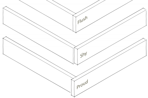
When you have to line up two pieces of material to create a corner, your pieces may be either flush, shy or proud. The illustration below shows:

Flush, Shy and Proud Flush, Shy and Proud
A piece is flush when it lines up with the outside face of the other piece. A piece is shy when it is inset from the outside face, and proud when it sticks out a bit.
 
Back
Top