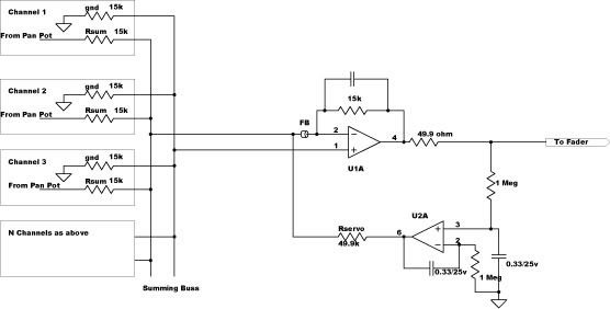
I was looking to find some tech about. To be honest I'm not sure what's that  I know that ssl did some quasi balanced "upgrade' on the 4k desks and that was something with ground.... Really like to know some more
You are using an out of date browser. It may not display this or other websites correctly.
You should upgrade or use an alternative browser.
You should upgrade or use an alternative browser.
quasi balanced summing
- Thread starter Moby
- Start date
Help Support GroupDIY Audio Forum:
This site may earn a commission from merchant affiliate
links, including eBay, Amazon, and others.
NewYorkDave
Well-known member
Andy Millar (ex-SSL, co-designer of the 4K) talked about it here. Search his posts. And if I remember correctly, there's also some coverage of it in Steve Dove's "Consoles and Systems" chapter in The Handbook for Sound Engineers.
Yes, I know, it's here
http://www.groupdiy.com/index.php?topic=159325&highlight=#159325
But I don't understand idea with (resistor "ladders" and "coathanger" mods) and replacing all of the lower buss cards (adding the 15K resistor packs).
comment by SSL tech. (Keith)
Maybe some drawing about can help.
Keith are you around :roll:
Unfortunately I don't have "The Handbook for Sound Engineers" :?
That's how I understand quasi balanced summing. Maybe I'm wrong :?


but wouldn't it be more 'accurate' if there were 2 virtual ground summers (one for signal and other for 'grounds') - sort of like 'upside down' instrument amplifier - i.e. 4 opamps (with dc servo). I guess such thing would work well with full balanced busses as well?
or would the whole thing require dc servos right on both summers (i.e. 5 opamps)?
or would the whole thing require dc servos right on both summers (i.e. 5 opamps)?
I just wonder is this "quasi balanced summing"? Forget about DC :wink:
TomWaterman
Well-known member
Moby, your drawing is how I imagined it after reading Paul Wolff's description of what he does in the Tonelux stuff.
My limited understanding is that it works in a way that is akin to adding an impedance balanced output to each module/channel that feeds the quasi-balanced bus with a diff. input sum amp for better noise performance.
Quite how the summing works as a differential amp I do not understand...at all, and would love to hear an explanation.
Tom
OK, part of drawing with DC servo is wrong and confusing :?
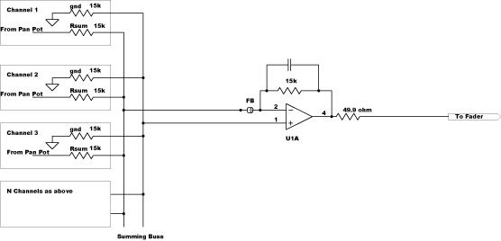
Let's try this way... Is this quasi balanced summing?

Let's try this way... Is this quasi balanced summing?

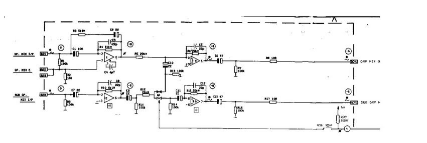
Calrec uses this technique in the UA-8000 board - it's a way of separating the mixbus reference from the 0V/Ground rails. Here's a (large) schematic of the meter section - in the upper left corner you will find the pseudo-balanced group mix amp (GP mix I/P & GP MIX E) very simple, based on a single NE5534 opamp. Sounds very good indeed - I've used this scheme for several other mixing purposes too.
http://img.photobucket.com/albums/v172/gyraf/Calrec_UA8000_Routing_and_meter.gif
Jakob E.
http://img.photobucket.com/albums/v172/gyraf/Calrec_UA8000_Routing_and_meter.gif
Jakob E.
NewYorkDave
Well-known member
Moby, in your second schematic, add a 15K resistor from "+" input to ground.
Thanks guys, now i get it. I hope... :?
Here's the crop of the (GP mix I/P & GP MIX E).

I presume that summing resistors are 10k.
Confusing part to me is GP MIX E , R22 and R23. What for two ports, and are they looking to ground via 10k too?
Here's the crop of the (GP mix I/P & GP MIX E).

I presume that summing resistors are 10k.
Confusing part to me is GP MIX E , R22 and R23. What for two ports, and are they looking to ground via 10k too?
[quote author="cuelist"][quote author="Moby"]Confusing part to me is GP MIX E , R22 and R23. What for two ports, and are they looking to ground via 10k too?[/quote]
Eh... those are connections - not resistors.[/quote]
Of course, the r21 is connector for summing resistor network, so i ask are R22 and R23 are connected to the network too?
Eh... those are connections - not resistors.[/quote]
Of course, the r21 is connector for summing resistor network, so i ask are R22 and R23 are connected to the network too?
Maybe I'm missing something, but the method of mixing using dual virtual earth amplifiers has been covered here before...... :guinness:
The 'superbal' amplifier deals symetrically with a balanced bus, and as long as the reference ground connection is good, it's impervious to ground current interference, it's got 6dB more headroom (as good as 60V rail!), It's quiet and well behaved over very long runs.... I wouldn't design a mixer any other way.
As an example of its flexibility, I once designed a talkback/monitor system for a major London studio using unscreened pairs operating in balanced 'virtual earth'. with hundreds of metres of wire; it was clean, quiet and trouble free.
Svart
Well-known member
I hope no one gets upset that I am going to ask for a thread reference without searching.. :shock:
EDIT: i see someone beat me to it.. :green:
EDIT: i see someone beat me to it.. :green:
I can't find the previous thread.... maybe it was the wrong forum! :?
But I have done a sketch of the balanced mixer I use.... if anyone would like a copy, or publish it here, then pls drop me an email at [email protected]
Pls feel free to use it. :guinness:
Ted Fletcher
But I have done a sketch of the balanced mixer I use.... if anyone would like a copy, or publish it here, then pls drop me an email at [email protected]
Pls feel free to use it. :guinness:
Ted Fletcher
Svart
Well-known member
Ok,
TedF has been gracious enough to allow me to host this for the forum!
http://www.theopiumdenproductions.com/balmix.jpg
Enjoy!
TedF has been gracious enough to allow me to host this for the forum!
http://www.theopiumdenproductions.com/balmix.jpg
Enjoy!
Thanks for that Svart......
Note... this is just the basic circuit; it would be sensible to add a few pF across the feedback paths (both the pairs of 3K3 resistors), but don't restrict the bandwidth of the inverter (the upper section of the MC33078).
The gain control is really a gain trim.... it has a limited range, but it's interesting because it retains the 'floating' nature of the circuit. :grin:
For the ultimate in low noise, you could reduce the series input resistors from 10K down to say 3K3, but this would mean reducing the feedback components too, and running into possible loading problems.... the MC33078 gets uncomfortable at frequencies above 10KHz if the output load starts to approach 2K2. The values shown seem to be a good compromise.
But the main advantage is the removal of any reliance on ground paths from the channels to the mixing amplifier; this has a miraculous effect on perceived quality on larger mixers.
Similar threads
- Replies
- 4
- Views
- 391
- Replies
- 16
- Views
- 725


