Quesiton about Bo's JFET Buffer

GroupDIY Audio Forum

Help Support GroupDIY Audio Forum:

This site may earn a commission from merchant affiliate links, including eBay, Amazon, and others.

Ethan

Administrator
Admin
Moderator
Joined
Jun 3, 2004
Messages
1,602
Location
DC
Could I use this circuit with a bipolar supply (+/- 20V) without modifications (other than changing the ground reference to the neg supply?) Would the only other modificaiton require having the 1M load resistor referenced to ground and getting rid of the pot?
FET%20impedance%20converter.jpg
 
Fets need very different voltages on gates for the same drain current, so trimpot is the clever idea to bias it, except some noises it can introduce potentially. No advantage from 40V, also some FETs may be broken by such a voltage. However, you may use bipolar power source, in such case value of the resistor in drain (instead of the pot) must be higher for the same current. Resistor from gate should be connected to the ground, and input and output signals ground referenced. But total voltage may not exceed specs for your FET.
 
Thanks Wavebourn.
No advantage from 40V
Wouldn't the higher rail voltages allow for higher signal swing? ...provided that the particular fet can tolerate the voltage.
 
[quote author="Ethan"]Thanks Wavebourn.
No advantage from 40V
Wouldn't the higher rail voltages allow for higher signal swing? ...provided that the particular fet can tolerate the voltage.[/quote]

Yes, it is obvious. What resistance are you going to drive, and what voltage swing do you need?
 
I want it to be able to swing about 35Vpk-pk and drive a 20K load. With the modificaitons, would using the above be OK?
Thanks.
 
[quote author="Ethan"]I want it to be able to swing about 35Vpk-pk and drive a 20K load. With the modificaitons, would using the above be OK?
Thanks.[/quote]

10K from -20V rail on 20K load will give maximum 20*20/30= 13V

I would suggest you to load your source follower by a constant current source capable to give you 35V p-p on 20K load, it is 1.75 mA

If you drive a cable, add it's impedance on higher end of spectrum in parallel and recalculate maximum current. But I don't like to drive capacitive loads by emitter-source-cathode followers, they sound horrible. Some additional resistor in series with load may help to reduce introduced distortions, but it will roll of highs. To calculate the compromise maximum allowed roll-off on 20 kHz is needed also.

For 40V and 3.5 mA dissipation on both transistors will be 40*1.75=70 mW, or 35 mW per each.
 
[quote author="Ethan"]Thanks Wavebourn.
No advantage from 40V
Wouldn't the higher rail voltages allow for higher signal swing? ...provided that the particular fet can tolerate the voltage.[/quote]
Not in this case. The circuit is biassed so the FET output is at 5V so the output swing can never be greater than plus or minus 5V not matter what the supply voltage.

Ian
 
So you might want to try a circuit like this (i haven't built or tested it and it may need work):

fet_source_follower.gif


The maximum current needed to produce a swing of 35vpp in the load is +- .875ma by Ohm's law, so the current source needs to produce at least that much. The fets need to be able to withstand a source to drain breakdown of at least 40V.

I need to disagree with a statement above. Emitter/source/cathode followers have been a common method of driving capacitive (and inductive) loads since the dawn of high fidelity.
 
[quote author="burdij"]
I need to disagree with a statement above. Emitter/source/cathode followers have been a common method of driving capacitive (and inductive) loads since the dawn of high fidelity.[/quote]

The more people disagree, the more I have a butter on my bread. ;)

Thanks! :D

Way before the dawn of high fidelity cathode detectors were popular. They exploited the idea of difference of output dynamic resistance of cathode followers in different directions. So, you may disagree with my proposal to use resistor in order to minimize impact of load capacitance on distortions that cause so called "Transistor Sound", you may love it, when I don't.
 
[quote author="burdij"]Which would be more like this?[/quote]

Yes, although you may need to tweak the bias on the gate of the upper FET--but halfway between the supplies is about where you want it to be. Or, if you want, you could use self-bias on the upper FET.

1/Gm is a good starting point for the drain resistor, but be prepared to adjust it by experimentation. The source resistor should be adjusted so that the follower idles at whatever peak current is needed to drive the load to the required level--or more.
 
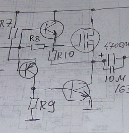
This is what I use to drive complex loads, from lines to speakers.

follower.gif


Emitter and source followers work in parallel loaded by a current source that follows input signal. Anyway, sometimes resistor in series with capacitive load helps to minimize distortions on high end of the frequency band.
 
[quote author="burdij"]What would be a useful parameter to monitor when adjusting the drain resistor, THD?[/quote]

Yes, but anyway it is a feedback loop so phase shift of the current on highs will impact on sonic quality. Also, rectifying effect because of such arrangement will be higher than with a stable current source, or mine (see photo).
 
Ethan,

Can you tell something about the application you shall use this "lardge headroom" FET-follower for.

It is easy to get the haedroom with high supply voltage, but usual JFET:s can not handle very high "Vds" voltage, (normally 25 to 40 volt) so it is important to be careful when you use them near the "max Vds limit value"

Ok, you can add a extra JFET as a "floating cascade" on the drain of the "normal" source follower JFET, to divide the voltage between both of them.
(or as the guys have talk about here before, to use some type of a " White JFET follower")

But if you use a MOSFET as a soure follower, you can run it on a very high voltage, (IRF510, Vds=100v or IRF610, Vds=200v) and get a huge headroom/swing, and if the PSU can give lardge current, you can load a MOSFET a lot.

--Bo
 
[quote author="Bo Hansén"]and if the PSU can give lardge current, you can load a MOSFET a lot.

--Bo[/quote]

...or you can load it just enough for better error compensation: http://www.groupdiy.com/index.php?topic=225417#225417
one hundreds of percent of the 2'nd harmonic, higher order harmonics below noise level.
 
Yes, perhaps for this application, MOSFET devices would be more appropriate. It would depend on the noise figure requirements on the input side. There are some JFET devices with 50V or better breakdown voltages in the 2N36xx range, but I think these parts are obsolete now. No problem for me because I think I have a box of a few hundred out in the garage. A 40V device might be usable but it would be chancy.
 
Thanks for all the responses guys!
I have just pieced together ideas and played with this in a simulator, but of course i don't know enough to know if it's lying to me and telling me that it will work.
How does this look, using J112's?
JfetBuffer.gif
 
Short 240 Ohm that goes to the + rail, you don't need it.
Otherwise looks like a doctor prescribed, however 10K load on the picture is for simulation only, also decoupling capacitor on output will be still needed.
 
Back
Top