Racking Studer 980 channel strip help.

GroupDIY Audio Forum

Help Support GroupDIY Audio Forum:

This site may earn a commission from merchant affiliate links, including eBay, Amazon, and others.

bxt403

Well-known member
Joined
Jan 9, 2009
Messages
65
Location
Calgary, AB Canada
I'm in the process of racking up my second Studer channel strip (as I managed to rack a 961 strip that was actually made to fit a 963- in that I had to modify it to get it to work).

W.r.t. the 980: I managed to wire up everything on a single strip I purchased before realizing that the strip doesn't seem to function (or if the on-board CPU requires communication with the main Central Control CPU that controls the mixer).  Nothing lights up or seems to work- it's only then I realized that the 980 might be like the 990 (in that a channel strip won't work without the central CPU).

From what I can deduce: the 980 uses a PIC ucontroller (that I assumed would be able to function independent to the Central Control Unit that controls the entire 980). It doesn't seem to be the case (and the power supply I'm using s providing VCC and LED voltages- along with the 15 Volt rails).

I'm wondering if anyone out there can confirm whether the 980 strip can be modified to work independently (through recoding the PIC processor or jumpering pins on it) or if it's a lost cause- @ least w.r.t. getting the LED's and switches to work. That is- I'd have to actually modify the strip to be entirely analog (which is more or less a lost cause). 

Any help with figuring out how I can get the PIC 17C42 to work without having to recode the firmware (or if it'll even function without being connected to the 980's Central Control Unit) would be greatly appreciated.
 
I forgot to wire the GND-REF connection (even though I marked it off on the schematic):  all the LEDs and switches light up.

The only problem is that a power supply resistor started smoking  as I was trouble-shooting so I need to replace it before I pass any audio through it but (all-in-all) the installation is fairly straight forward (albeit the AUX 7-8 pot is acting as the master fader that's feeding a modified CR-monitor Euro-card).

At least I can occupy my time by pressing all the switches and watch them light up...
:p
 
Not intending to derail your thread... but I have myself been trying to get a pair of 961 strips racked up but without any luck.  I'm wondering what kind of grounding hookup you did for that... There a lot of grounds and although I've tried a few schemes that seemed intuitive, the best I've gotten is all the LEDs stuck on and certainly no signal passing through.  Perhaps I need to draw the logic rail from a different transformer, as someone in a thread about a 900 racking thread mentioned, but I'd like to know i've got the grounding situation correct... thanks if you have any tips
 
Just get the schematic from the Studer ftp (it's free to download and login as Guest)...Aside from chasis ground (and depending on how you're producing the -6 VDC LED ground)- you just need to daisy-chain every non-chasis ground point from the power supply ground.  It's probably a good idea to connect a separate cable (from the same power supply ground point) to the "Ground Reference" connection that goes to an op amp).

It's straight-forward when you look at the pinout in the service manual.

I got the 980 working by connecting to the "Ground Reference" connection (that I neglected to connect but mark off for connection). 
 
I started a same project, but I have some questions... (Studer 980 - 1.980.220.101)
Is it OK to hardwire the P3A 01A pin to P4 28A/28B and so on? Are they on the same supply? According to the service manual, the P3A 01A is -15V, but the P4 28A is -15,5V.

If I'm right, I have to create these supply voltages:
+ 15V
- 15V
+ 5 V (VCC)
+ 3..4 V (for LEDs)

Do I have to make +-15,5 V and +5,5V?
 
LOmmPA said:
I started a same project, but I have some questions... (Studer 980 - 1.980.220.101)
Is it OK to hardwire the P3A 01A pin to P4 28A/28B and so on? Are they on the same supply? According to the service manual, the P3A 01A is -15V, but the P4 28A is -15,5V.

If I'm right, I have to create these supply voltages:
+ 15V
- 15V
+ 5 V (VCC)
+ 3..4 V (for LEDs)

Do I have to make +-15,5 V and +5,5V?

I've repaired those modules before, and I was able to make them work independently of the console.

I remember at that time I used the information on a thread that was here in the forum

that was enough to make the module work, search around a try to find that thread, valuable info there
 
LOmmPA said:
I started a same project, but I have some questions... (Studer 980 - 1.980.220.101)
Is it OK to hardwire the P3A 01A pin to P4 28A/28B and so on? Are they on the same supply? According to the service manual, the P3A 01A is -15V, but the P4 28A is -15,5V.

If I'm right, I have to create these supply voltages:
+ 15V
- 15V
+ 5 V (VCC)
+ 3..4 V (for LEDs)

Do I have to make +-15,5 V and +5,5V?

If you look at the power supply section for the module, you'll see that the +/- 15V supply is derived from the +/-15.5V on the module (for my module it's page 298 of the pdf labelled 9a of 13 in the CAD drawing). 

I only supplied 3.5V, and +/-15.5V to P4-29A and 28-A respectively (you'll see that the +/-15V pins connect to them after some blocking diodes capacitors and resistors).  It looks like the P3 +/-15V pins short at R160 and R154 (so you should be able to verify they're derived from the +/-15.5 pins with a multimeter). 

The grounding is a bit more problematic in that I remember I needed to have the 0V REF pin connected to get the module working.

I forgot to add that the only way you can get audio out from the module (without the external fader module) is via the balanced insert(s).  That is- you need the fader module to use any of the AUX channels (refer to the block diagram on page 274 of the pdf).

I'm quite certain the LED voltage is 3 to 4 Volts (it's in "European" in that a comma's a decimal: notice +/-15.5 is listed as +/-15,5).  The LED's voltage is listed as 3_4 which I interpret as 3-4 (or 3 to 4 Volts).  You should be fine with 3.4V but you can probably go as low as 3V and as high as 4V.  I'm using 3.5 without any issue (I just prefer sticking to the mean voltage value knowing Studer has listed all the decimals as commas and the value listed is clearly "3_4" not "3,4") .   
 
bxt403 said:
If you look at the power supply section for the module, you'll see that the +/- 15V supply is derived from the +/-15.5V on the module (for my module it's page 298 of the pdf labelled 9a of 13 in the CAD drawing). 

I only supplied 3.5V, and +/-15.5V to P4-29A and 28-A respectively (you'll see that the +/-15V pins connect to them after some blocking diodes capacitors and resistors).  It looks like the P3 +/-15V pins short at R160 and R154 (so you should be able to verify they're derived from the +/-15.5 pins with a multimeter). 

The grounding is a bit more problematic in that I remember I needed to have the 0V REF pin connected to get the module working.

I forgot to add that the only way you can get audio out from the module (without the external fader module) is via the balanced insert(s).  That is- you need the fader module to use any of the AUX channels (refer to the block diagram on page 274 of the pdf).

I'm quite certain the LED voltage is 3 to 4 Volts (it's in "European" in that a comma's a decimal: notice +/-15.5 is listed as +/-15,5).  The LED's voltage is listed as 3_4 which I interpret as 3-4 (or 3 to 4 Volts).  You should be fine with 3.4V but you can probably go as low as 3V and as high as 4V.  I'm using 3.5 without any issue (I just prefer sticking to the mean voltage value knowing Studer has listed all the decimals as commas and the value listed is clearly "3_4" not "3,4") . 

Thank you very much for the detailed answer!
I'll try this method soon!
 
Just two more questions:

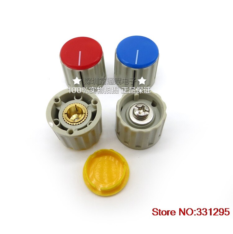
1, Is there a special method to remove the potentiometer knobs? I'd like to clean them but I can't remove any of the knobs and I don't want to brake a pot...

2, What power supply do I need (for one input module)? 20-25W is enough?

 
LOmmPA said:
1, Is there a special method to remove the potentiometer knobs? I'd like to clean them but I can't remove any of the knobs and I don't want to brake a pot...

20PCS-High-quality-knob-potentiometer-switch-cap-110E-flip-lock-screw-red-yellow-and-blue-gray.jpg
 
LOmmPA said:
Just two more questions:

1, Is there a special method to remove the potentiometer knobs? I'd like to clean them but I can't remove any of the knobs and I don't want to brake a pot...

2, What power supply do I need (for one input module)? 20-25W is enough?

Depending on the module- you'll probably need something like 30 Watts for a stereo module while a mono one is likely more than half of that so I'm guessing 20 to 25 Watts.  I went with the JLM AC/DC kit for my build.

The pots are quite easy to take off- you just need to remove the tops of the knobs with a flat-head jeweller's screwdriver  or something similar (be careful not to leave any tool marks- I recommend trying the AUX knobs first).  You'll see the screw underneath (it's recessed in the knob) but keep in mind that the pots are round so you'll want them set to either maximum or minimum before you unscrew the knobs off.
 

Latest posts

Back
Top