You are using an out of date browser. It may not display this or other websites correctly.
You should upgrade or use an alternative browser.
You should upgrade or use an alternative browser.
RCA BC-2B
- Thread starter buildafriend
- Start date


Help Support GroupDIY Audio Forum:
This site may earn a commission from merchant affiliate
links, including eBay, Amazon, and others.
buildafriend said:I was on the phone with Cinemag selecting an output transformer for this BA-2. Dave was nice enough to look at the schematic and said:
"Hi Jon;
I think that you can live with a turns ratio of 4:1. The CM-2810 with steel laminations and butt-stacked should work well. $40.55 If you know how much dc current it will take, that can help me figure out the amount of gap it needs.
-David"
Should I assume that the DC current that the the OP transformer will be taking is the exact amount that the PSU is dishing out? 250-300V DC.
That's not the DC current, it's the voltage. You can build this with a steel 4:1 that passes 5 mA at 220V (off the top of my head, in the manual), but it won't sound or act like the original 7-10:1 nickel/steel output. It may be close enough. One of these BC-2 threads dissects current flow, and ratio, find it.
dmp
Well-known member
Interesting. Thanks for the great info. With a different PT the situation may be different? I'm using Antec, http://www.antekinc.com/details.php?p=670. The spec sheet does not give DCR but I could measure it.The datasheet for 6X5 indicates a 4uF head capacitor. The RCA choice of using 40uF is justified by the fact that it runs at 2/3 of the rated voltage and that the transformer has 700 ohms DCR for each half-secondary. I bet you could fit a 47uF without further ado, but, as always, there's the risk of optimism, so you could use a 33uF. Remember that very often, elcap values were overrated because designers knew that the value would decrease with age. Today, elcaps are much more stable, so your 33uF will be equivalent to a 5 years old 40uF of period technology. And anyway, you're free to compensate the relatively feeble value by incresing the other caps that follow. C4=33uF and C5=C6=47uF should be adequate.
As this is an inductance coupled output stage (correct?) I'd think the rejection of power supply noise might be better than resistance coupled???
I was on the phone with Cinemag selecting an output transformer for this BA-2. Dave was nice enough to look at the schematic and said:
"Hi Jon;
I think that you can live with a turns ratio of 4:1. The CM-2810 with steel laminations and butt-stacked should work well. $40.55 If you know how much dc current it will take, that can help me figure out the amount of gap it needs.
-David"
Should I assume that the DC current that the the OP transformer will be taking is the exact amount that the PSU is dishing out? 250-300V DC.
I'm still not 100% here and perhaps some others with more in depth transformer knowledge can chime in, but here goes:
I have also just been speaking with David regarding another Cinemag model for SE use and trying to determine if it will meet spec of the original RCA. Without furnishing an L number at some test frequency I'm not sure where to begin. (He did not have one on hand and it wasn't documented)
For sure you will running the tube at, call it 4ma. Also know that at that current the plate resistance of the 1620 (triode) will be somewhat high. I haven't found a data sheet with the rp vs current curves for triode strapped 6J7/1620 but I assume it to be comparable to other similar low mu triodes. NYDave once calculated it to be around 12K. A 6C5 looks closer to 14K. That calls for a hefty L to stay "flat" to 30Hz in a no NFB circuit. When David says "It will take X amount of current", I'm not sure if he means the amount of current it can take with no loss of L, negligible loss of L?, or what. Either way I think we need a measured L figure for the pri to see where we will stand. So, I'd ask specifically for that and maybe mention a source impedance figure (the plate resistances I mentioned above). Or, stated another way, you want response within say 0.5 db to 30Hz with a given source Z @ 4ma unbal DC. 4:1 seems to work fine. That's an A-25, which is what myself and some others have used.
The PSU just "supplies" based on the circuit load - ie treat as one big resistor which can be calculated based on the current that each tube draws more or less. The supply is just like a reservoir.
SCHEMATIC http://www.coutant.org/ba2c/index.html
May be a good idea to move to BA-2 thread or clarify some other way. I wasn't sure for a while but sounds like this a BA2 project.
That is a good idea; that will give you one more parameter. If the DCR is lower than 700r, you may want to introduce a series resistor to limit the inrush current.dmp said:The spec sheet does not give DCR but I could measure it.
It is really a transformer-coupled output...As this is an inductance coupled output stage (correct?)
...as such, it doesn't have the benefit that inductor-coupled stages have, because the ripple voltage (that would be somewhat filtered in an inductor coupled stage) is integrally reflected at the secondary.I'd think the rejection of power supply noise might be better than resistance coupled???
True, but you have to take into account the reflected load impedance, which appears in parallels with Rp, so you end up with a significantly lower value, typically about half.lassoharp said:A 6C5 looks closer to 14K. That calls for a hefty L to stay "flat" to 30Hz in a no NFB circuit.
The answer is simple in its formulation; the inductance with DC flowing must be consistent with the Rp/Rload calculation.When David says "It will take X amount of current", I'm not sure if he means the amount of current it can take with no loss of L, negligible loss of L?, or what.
Simple answer, but in practice, there are several answers; you can't expect the mfgr to publish the whole family of curves L vs. DC current vs. signal amplitude vs. frequency.Either way I think we need a measured L figure for the pri to see where we will stand.
That's what one ends up doing in practice; it is somewhat less fulfilling, but OTOH, that's what happens when you select a product in a catalogue, as opposed to designing one from scratch.So, I'd ask specifically for that and maybe mention a source impedance figure (the plate resistances I mentioned above).
Now, you're completely spoiling the game!Or, stated another way, you want response within say 0.5 db to 30Hz with a given source Z @ 4ma unbal DC. 4:1 seems to work fine. That's an A-25, which is what myself and some others have used.
Thank you abbey road for sorting out those loose ends!
I surely missed that. Now that's really spoiling the game! - from a design POV. Seems to make things a little bit easier as far as the game of trying to get lower source Z by running more current through the tube and watching the benefits go to pot because of the need for more $$ OTs. And we usually don't need more than the 4ma or so for most applications.
meaning as long as the L doesn't start to fall due to the effects of unbal current? The limits of the transformer design?
Yes, that's what I was having trouble sorting out. Without the effects of unbal DC, I'm understanding it as mainly a matter of source impedance vs L for estimating the low freq characteristics. And at some point the effects of DC start causing the L to fall - I guess a good example would be the UTC A-25 -15K:600, rated as "flat" to 40Hz with an allowable unbal DC of up to 8ma. Is it correct to interpret this as: assuming a source impedance of roughly half the pri, you will have sufficient L to get "flat" to 40Hz for any value of unbal DC up to 8ma? And plot your own demise once you exceed the 8ma?
True, but you have to take into account the reflected load impedance, which appears in parallels with Rp, so you end up with a significantly lower value, typically about half.
I surely missed that. Now that's really spoiling the game! - from a design POV. Seems to make things a little bit easier as far as the game of trying to get lower source Z by running more current through the tube and watching the benefits go to pot because of the need for more $$ OTs. And we usually don't need more than the 4ma or so for most applications.
The answer is simple in its formulation; the inductance with DC flowing must be consistent with the Rp/Rload calculation.
meaning as long as the L doesn't start to fall due to the effects of unbal current? The limits of the transformer design?
Simple answer, but in practice, there are several answers; you can't expect the mfgr to publish the whole family of curves L vs. DC current vs. signal amplitude vs. frequency
Yes, that's what I was having trouble sorting out. Without the effects of unbal DC, I'm understanding it as mainly a matter of source impedance vs L for estimating the low freq characteristics. And at some point the effects of DC start causing the L to fall - I guess a good example would be the UTC A-25 -15K:600, rated as "flat" to 40Hz with an allowable unbal DC of up to 8ma. Is it correct to interpret this as: assuming a source impedance of roughly half the pri, you will have sufficient L to get "flat" to 40Hz for any value of unbal DC up to 8ma? And plot your own demise once you exceed the 8ma?
Yes; that's as simple as that: as soon as DC hits the xfmr, the inductance decreases. How much and how rapidly depends on several choices, typically the nature of the core material and the influence of the air gap. Each mfgr has its own receipe, and even for the same xfmr model, there could be differences, because the actual air gap depends on the pressure with which the core is assembled, each lamination is different from another, and so on.lassoharp said:meaning as long as the L doesn't start to fall due to the effects of unbal current?The answer is simple in its formulation; the inductance with DC flowing must be consistent with the Rp/Rload calculation.
Because of all these variable parameters, the xfmr designer must apply a worst case factor, so an average xfmr should be better than specs in most cases. The concept is that the worst combination of tolerances should still result in a usable xfmr.The limits of the transformer design?
That's exactly what it is. The problem is that L varies with DC mag, with signal amplitude, and to a lesser amount with frequency, in a manner than can hardly be described with simple linear equations, so the designer will make his design work within limits that he has to define - hopefully these limits will be corresponding to a desirable configuration.Without the effects of unbal DC, I'm understanding it as mainly a matter of source impedance vs L for estimating the low freq characteristics. And at some point the effects of DC start causing the L to fall
Yes, and, as emrr says, it is not a brutal transition, it is a continuous but non linear behaviour. I can estimate that the same xfmr, with only 2mA, would go down to about 30Hz at the same reference level.- I guess a good example would be the UTC A-25 -15K:600, rated as "flat" to 40Hz with an allowable unbal DC of up to 8ma. Is it correct to interpret this as: assuming a source impedance of roughly half the pri, you will have sufficient L to get "flat" to 40Hz for any value of unbal DC up to 8ma? And plot your own demise once you exceed the 8ma?
buildafriend
Well-known member
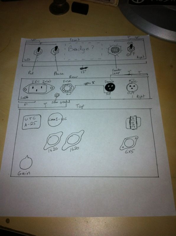
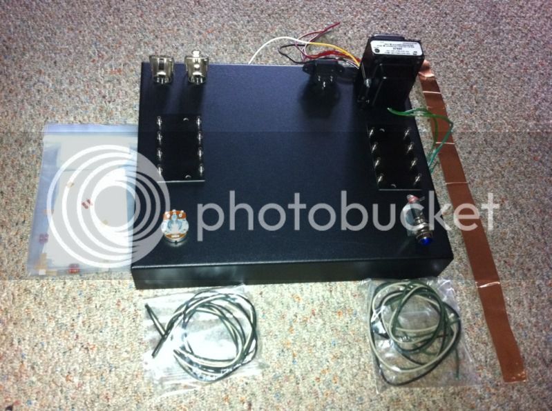
here is a rough idea for the external parts layout. I am bearing in mind that I want to keep my heater wires and power as far away from my audio as possible. That is why power is far right, and audio is far left. Any turret boards that I use will be near or underneath my tubes.
buildafriend
Well-known member
a few things that I don't understand about this circuit:
No coupling caps. its okay to let the DC hit the transformers?
No diode bridge. how can you get DC?
Is the lead between R1 and R2 for a DI?
What the trace between R5 and R6 leading to?
Why are C3 and C1 low voltage caps?
I thought that heaters only took positive power and hit ground... I never noticed that there is a negative side. The polarity of this does not matter does it?
Sorry for being a newb to old tube technology. Thanks regardless.
buildafriend
Well-known member
hmm okay, ill move my questions to the proper thread. thanks.
EvLoutonian
Well-known member
- Joined
- Jul 8, 2010
- Messages
- 197
Cool to see this project ..
I just picked up an AWA BUC-1 console, which is almost identical to the RCA BC-2B.
(I believe AWA had a licensing deal with RCA, to produce, assemble, or replicate some designs from RCA, for the Australian broadcast industry here in the 1950's etc).
So this console has three of the dual pre-amp modules .. . Nice to find some reference material out there, as this thing is gonna need some restoration.. I just hop all the transformers are OK!
EvLoutonian said:Cool to see this project ..
I just picked up an AWA BUC-1 console, which is almost identical to the RCA BC-2B.
(I believe AWA had a licensing deal with RCA, to produce, assemble, or replicate some designs from RCA, for the Australian broadcast industry here in the 1950's etc).
So this console has three of the dual pre-amp modules .. . Nice to find some reference material out there, as this thing is gonna need some restoration.. I just hop all the transformers are OK!
Neat score! I would say the transformers should be fine, but I saw the photo on Instagram

Those RCA preamp outputs are notoriously bad when in a console; I'd say 33% on average I've encountered. I don't see them bad when they are on a BA-11 or BA-12. I strongly suspect it relates to the wide variations in power supply voltage possible when stations disconnect various parts of the console, particularly the practice of disabling the monitor amp in favor of an outboard, without compensating for the load change. This is true of the 76 series console preamps as well; frequently bad in the consoles, fine on the various standalone pre's that use the same output.
EvLoutonian
Well-known member
- Joined
- Jul 8, 2010
- Messages
- 197
emrr said:Those RCA preamp outputs are notoriously bad when in a console; I'd say 33% on average I've encountered.
Ah, thanks Doug ..
So, do you mean, output transformer getting "cooked" from too much voltage being passed into them?
Similar threads
- Replies
- 4
- Views
- 890