Repairing Mackie CR1604VLZ, burnt transistor?

GroupDIY Audio Forum

Help Support GroupDIY Audio Forum:

This site may earn a commission from merchant affiliate links, including eBay, Amazon, and others.

ma_headphone

Member
Joined
Nov 30, 2017
Messages
15
Hi!

I've been replacing the ribbon cables on my Mackie CR1604VLZ to fix the well known issues related to them. After replacing them I heard generally a big improvement in the sound.

However, I did a mistake during the repair. During the replacement I inverted one of the ribbon cables, and I saw smoke coming out of the power/preamp board. I immediately turned off them mixer and fixed the cable direction.
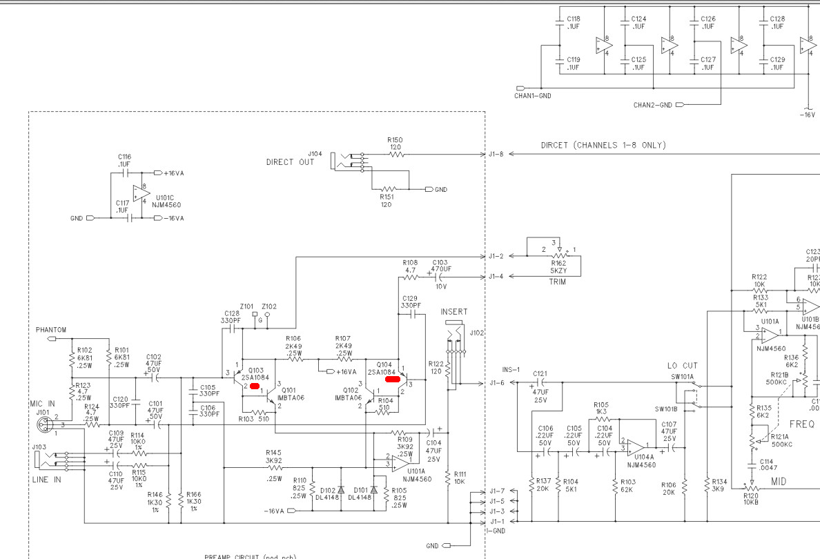
The result of this is that, when I power up the mixer, the 1st channel does not work anymore. There is also a loud buzz on the master, but all the rest seems ok. If I enter through and insert point on the 1st channel (thus bypassing the preamp) I can hear the sound, and I can also use the EQ. My suspicion is that there is an issue in the preamp/input section.

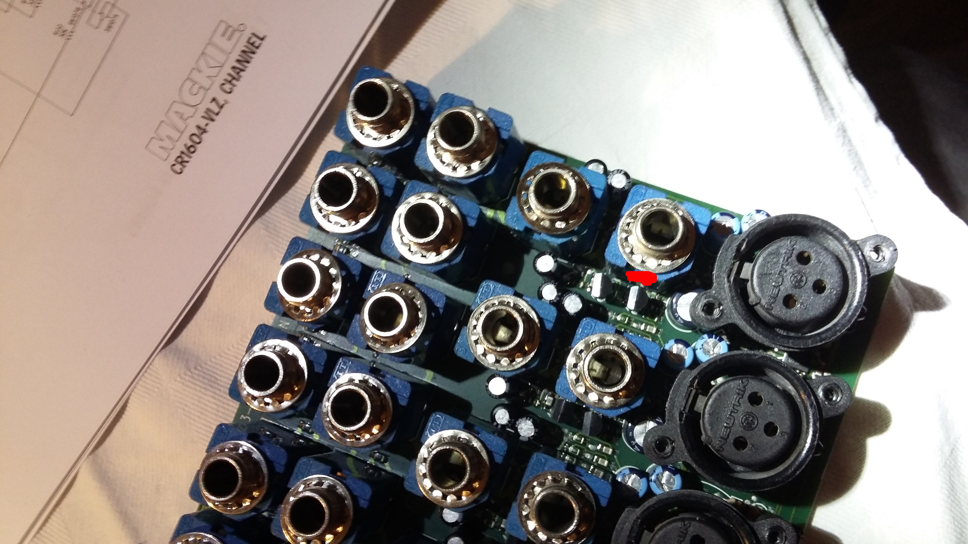
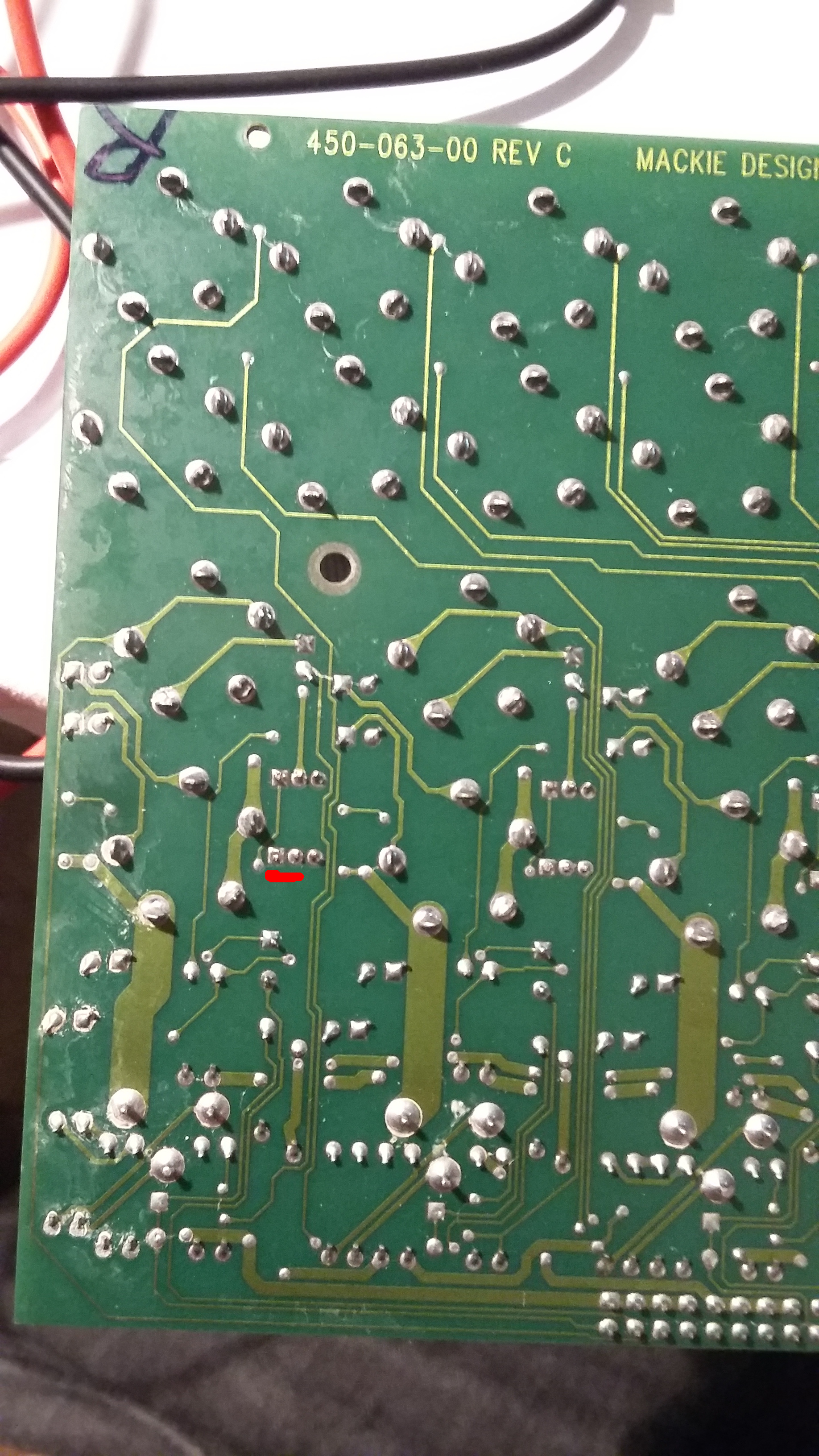
I checked the PCB and I think I found a fried PNP transistor. I checked the legs and it seems like 2 legs are shorted. I checked the legs on the transistors on other channels and there is 7K Ohm resistance between the legs.
I marked in red the PNP which I'm talking about. I'm not sure which of the 2 it is on the schematics, I guess the left one.

How shall I proceed, shall I just try replacing this transistor? Is there some other check I should do, maybe there is something else broken I should replace before turning on the mixer again?

The PCB has both SMD and through-whole components, I think I should be able to replace this PNP on my own, even though I'm not a soldering guru.

Thanks in advance!
schematics_185.jpg

frontside_382.jpg

backside_184.jpg
 
The 2sa1084 are specialized low noise transistors so if reverse biased, even if not broken, may exhibit higher noise so replace both...

The A06s look like cheap GP NPNs so won't break the bank to replace them too...

Lastly the op amp (4560) is also cheap and probably should be replaced.

I will resist the temptation to be unkind about Greg's children (mackie mixers).  Lots of people like them.

JR
 
> 2sa1084 are specialized low noise transistors

For diagnosis ("is this too burnt to be worth fixing?"), any jellybean PNP will work here. 4dB noise figure beats silence.

(Of course replacing with a 10 cent part,  then re-replacing with a $1 part, is abuse of a PCB which was never intended to be repaired.)

Agree that all the semiconductors, and any electrolytic caps, are at-risk and all too cheap to cry over. The real thing is your soldering skill and possible availability of "for parts" '1604's.

I liked the older value Mackies, including a '1204(?). Never put a ton of hours/years on one. He was maybe over-proud of fairly obvious circuit details ("VLZ" aint much), but there's worse gear out there.
 
Hi completely agree with PRR,
you should replace semiconductors and electrolytic caps, but the your soldering can really damage the board.

I worked on a lot of this mixer in the past, like PRR said the boards were not made to be repaired.
You will easily break solder pads and pcb traces when using the Iron. Remember also it's a double side pcb, so you have traces and pad on both sides.

The best think for this boards is using the Heatgun and a lot of soldering paste. But you need someone experienced to do that.

Do you have friend with good soldering experience? Can you Pay someone with experience just to solder and desolder you components?

It's better to pay than to damage the pcb 
 
Thanks a lot for the prompt feedback!

I did some more tests and I saw that when the power is on, the "broken" transistor has the following voltages:
E=-8V
C=-8V
B=0V

I checked the same transistor from a different channel and I found:
E=0V
C=-8V
B=0B

I guess this confirms my suspiction that there is a short between E and C?

I also checked the traces, I'm pretty sure it's the left one on the schematic. There is zero resistance between the emitter and the trim input. It's a bit hard to test other components, since the surface mount parts are in between the input jacks and it's hard to reach then without desoldering them.

I have ordered a bunch of 2SA1084 transistors from Ebay, I should get them within a few days. I'll try replacing this first and see what happens.

Now, this component is through-hole and I think I should be able to replace it myself.  The opamp is SMT , and even though I'd be happy to replace it for something better, I don't have neither the experience nor the tools to remove it.
I have a desoldering pump and a desoldering braid, I guess it should be enough to remove the transistor.
I could consider replacing the electrolytics, but maybe I'll keep this a second step.

The Mackie is a cheap mixer, but it works very well for me since it's compact and has a lot of I/O! Unfortunately it's not designed for easy repairs as you said. I could pay somebody to fix mine, but since I can get the same mixer for 220 Euros on the local second hand market, maybe it's not worth it! I'll try to fix this myself and if it doesn't work I can always get another one...

 
ma_headphone said:
Now, this component is through-hole and I think I should be able to replace it myself.
I have a desoldering pump and a desoldering braid, I guess it should be enough to remove the transistor.

Use this trick so you can safely remove the transistor:

Don't Desolder the broken transistor, you cut it's legs right under the plastic.
And then with a tweezer desolder and remove one leg at each time.

This method is much faster and will prevent pads&traces overheating, and if needed you can also provide heat on top and bottom of the board.

It works well for IC's also.
 
Last edited:
I tried to do some resistance readings with the multimeter. It was a bit tricky to reach the SMD parts, I did the best I could without desoldering the audio jacks. I'm not 100% sure of the correctness of all readings. Let me know if something looks odd!

From what I see: the value base-collector on the left PNP is really low, that's what I mentioned before.
The resistance between base and emitter of the NPN is also quite low but I guess it depends on the parallel of the resistance and the internal B-E resistance of the NPN (I guess 250ohms?)?
Same for the opamp, does it depend on the resistance on the feedback path and the opamp internal resistance (1150ohms?)?

I should do some theory basic review, and probably I also need a hot air gun now,  it would be good to be able to replace SMDs as well

attachment.php

 
If the VOM has a diode scale you should read diode drops (roughly 0.5V) from base to emitter and base to collector...  You will need to swap the + and - leads around for PNP and NPN transistors.

JR
 
I thought I was out of the know and didn't mention the diode function earlier... and he did mention finding a short so I was just following along.......

May as well check those couple diodes while you're at it as well...... Although I'm kinda lost on where the jumper in question is at....

Good luck!!!! I'm sure it's something simple... And you have schematics ....Could be worse....
 
Since you flipped a ribbon cable to cause the failure, you can exactly determine what voltages you stuffed into the connector to cause the smoke to get let out. Look at the pinout and see what became connected to what.

Chances are, if you reversed the supply voltages, or stuffed supply voltages into an un-powered semiconductor device, it's fried. Current went through paths that it was not supposed to, and if enough current passed for long enough, you've re-wired the chip permanently.  Even the ones that still seem to work can be degraded. So, a shotgun replacement might be in order, but it's still interesting to see which voltages went where and thus which parts are suspect, and which might not be damaged.

BTW, the same applies to diode or resistance mode from your DMM - it's stuffing current into places that might not want that to happen. If you can power up the device without any massive fault currents, it's a lot safer to look at the circuit voltages with the DMM's voltage mode, which is passive and will not further damage your device. A good place to heed caution is around the op amp inputs - they don't like reverse voltages or voltages beyond the power rails. OTOH, if you can power it up, check for burning components, and if there are none, then you can look at voltages and see what still works and what does not. For example, functioning op amps that are not used as comparators will have their two input terminals at nearly the same voltage, and also their output voltage somewhere not right next to the power supply voltages.

Still, a shotgun might be best. Removing the through-hole components with flush cutters and then clearing each hole is definitely wise. Much less stress on the PCB, even if you have really nice tools. The PCB is very valuable, the components, not so much, especially on that unit.
 
Thanks for the invaluable feedback and sorry for the delay.  I managed to get Voltage readings through the first channel preamp section, here you see them in a picture, listed in green:

attachment.php


There are few things I don't understand:
1) The left PNP has 8V on E and C. This is different from other channels, which have 0.6 on the emitter. I guess this is a short?
2) The pinout of the PNP is opposite as on what listed on this datasheet http://pdf.datasheetcatalog.com/datasheet/HitachiSemiconductor/mXwvssz.pdf
3) I don't get why there is -16V on the PNP Emitter instead of +16V as marked on the schematics I found.  This is the same on all channels. Note that all other channels are working fine.
4) I don't get why the voltage on the Emitter of the  PNP on the right is 0.6 instead of -8. Also other channels have 0.6V there.

I didn't find any burning hot component. Maybe only the opamp is slightly warm.

Btw, I did everything live on the board without desoldering. I think I can't test the diodes without desoldering them.

I will receive the spare 2sa1084 in the next few days. I'll replace the left one if you agree.
I'm checking out also for other replacement parts and a heat gun station, I'll make an order soon.
 
ma_headphone said:
Thanks for the invaluable feedback and sorry for the delay.  I managed to get Voltage readings through the first channel preamp section, here you see them in a picture, listed in green:

attachment.php


There are few things I don't understand:
1) The left PNP has 8V on E and C. This is different from other channels. I guess this is a short?

I'm only familiar with testing transistors using the DMM diode function . You check for shorts then pull transistor from circuit to make certain it is shorted because a bad resistor can even cause a transistor to look bad when it isn't. But I see this isn't recommended by some for good reason.

2) The pinout of the PNP is opposite as on what listed on this datasheet http://pdf.datasheetcatalog.com/datasheet/HitachiSemiconductor/mXwvssz.pdf

Something isn't adding up with that..... Are you looking at the actual transistor or how it's used in the schematic???


3) I don't get why there is -16V on the PNP Emitter instead of +16V as marked on the schematics I found.  This is the same on all channels. Note that all other channels are working fine.

Might be probing  wrong ???

4) I don't get why the voltage on the Emitter of the  PNP on the right is 0.6 instead of -8. Also other channels have 0.6V there.


That's a mystery?


I didn't find any burning hot component. Maybe only the opamp is slightly warm.


doesn't tell much

Btw, I did everything live on the board without desoldering. I think I can't test the diodes without desoldering them.

You can but always pull to verify a bad reading. But once again, some recommend against this


I will receive the spare 2sa1084 in the next few days. I'll replace the left one if you agree.
I'm checking out also for other replacement parts and a heat gun station, I'll make an order soon.

These are all guesses from me but, you should be checking those transistors and related components as best you can before getting into the hassles of removing components... More often than not, it's been the long road for me when I've taken that route......

The small IMBTA chip transistors...... sure are tiny
 
I'm really lost on this cirtcuit  :-[
FYI, I fixed a bit the last picture I sent.
I read a 24V drop on the 2.5K resistor between the +16 source and the NPN Collector. This confirms that the voltage is +16 on one side, and -8 on the other.

I will start desoldering and checking components one by one when I get the parts I'm waiting for, this will still take 1-2 weeks.
RIght now the measurements of the transistors and diodes are not easy to do, when their legs are on the PCB attached to other components..

Do you think the MMBTA06 are equivalent to the IBMTA06?
https://www.mouser.ch/ProductDetail/ON-Semiconductor-Fairchild/MMBTA06/?qs=sGAEpiMZZMshyDBzk1%2fWi8oN7VHZ91OkCPJkXb9HLWM%3d
I can't find a datasheet for the IMBTA06.
 
Actually, could the opamp be the problematic one? On a good channel I read -9V, -9V on the inputs, and 0V on the output. On a bad channel I read -9V, -9V on the input and -14V on the output ... mm  :-\
 
It's a normal multimeter, Philips MX-2008. I has the usual AC/DC/Ohm/Diode functions..
I also have a Picoscope, but I'm not sure if it's worth checking with that right now...
 
Q101 is definitely dead and Q103 ought not be trusted. Replace Q101 and test it, or to minimize headaches, replace them both.
 
ma_headphone said:
Thanks for the invaluable feedback and sorry for the delay.  I managed to get Voltage readings through the first channel preamp section, here you see them in a picture, listed in green:

attachment.php


There are few things I don't understand:
1) The left PNP has 8V on E and C. This is different from other channels, which have 0.6 on the emitter. I guess this is a short?
The voltage readings are consistent with Q101 being shorted collector-emitter.
2) The pinout of the PNP is opposite as on what listed on this datasheet http://pdf.datasheetcatalog.com/datasheet/HitachiSemiconductor/mXwvssz.pdf
3) I don't get why there is -16V on the PNP Emitter instead of +16V as marked on the schematics I found.  This is the same on all channels. Note that all other channels are working fine.
the pnp emitters should be +0.6V, the -8.9V is result of shorted Q101 pulling emitter negative and reverse biased. A typical base-emitter junction will zener at about -7V, but not that one apparently.
4) I don't get why the voltage on the Emitter of the  PNP on the right is 0.6 instead of -8. Also other channels have 0.6V there.
0.6V is correct...  replace Q101
I didn't find any burning hot component. Maybe only the opamp is slightly warm.

Btw, I did everything live on the board without desoldering. I think I can't test the diodes without desoldering them.

I will receive the spare 2sa1084 in the next few days. I'll replace the left one if you agree.
I'm checking out also for other replacement parts and a heat gun station, I'll make an order soon.
The 1084 may still work if it didn't zener, but reverse bias can make low noise parts noisy. 

JR
 

Latest posts

Back
Top