efinque
Well-known member
- Joined
- Jan 3, 2018
- Messages
- 368
Sup GDIY,
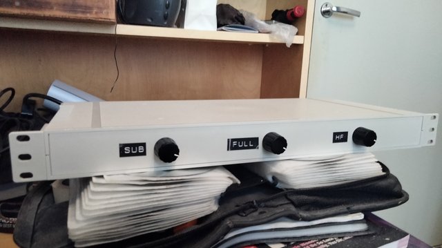
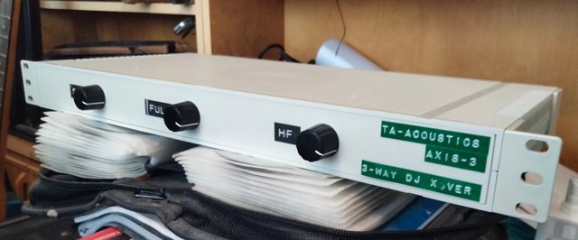
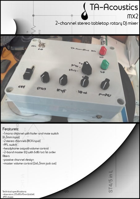
here's a build that's close to being finished, so far it's missing labeling. Afaik the original RLA units had RCA in/out, 24db/oct filters and a fullrange mid band. They were operated from the DJ booth. My take on this has 6,3mm jacks and 6db/oct filters.
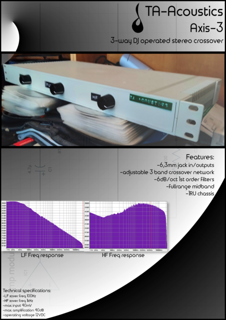
The crossover points are 400Hz LF and 800Hz HF.
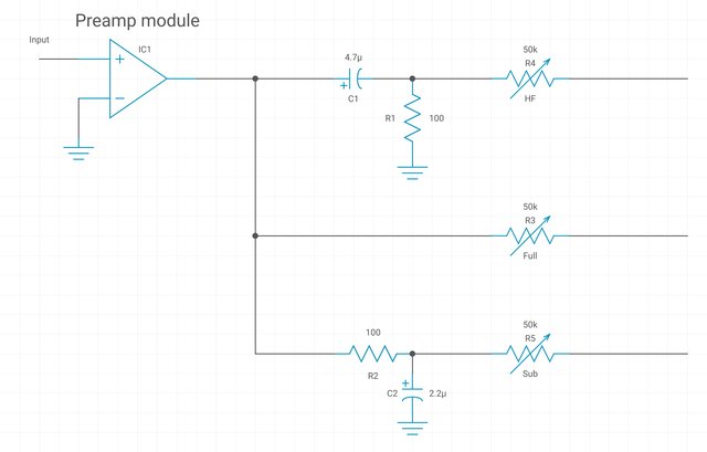
The preamp section is built from kits, I've yet to test them though. I jumped them with alligator clips to check the freq bands; the filters sounded sweet.
I'll try to post a schematic once I get an EDA software.
Any thoughts?
-ef
here's a build that's close to being finished, so far it's missing labeling. Afaik the original RLA units had RCA in/out, 24db/oct filters and a fullrange mid band. They were operated from the DJ booth. My take on this has 6,3mm jacks and 6db/oct filters.
The crossover points are 400Hz LF and 800Hz HF.
The preamp section is built from kits, I've yet to test them though. I jumped them with alligator clips to check the freq bands; the filters sounded sweet.
I'll try to post a schematic once I get an EDA software.
Any thoughts?
-ef