Rolls MP13 Mini Microphone Preamp - How To Reduce Gain?

GroupDIY Audio Forum

Help Support GroupDIY Audio Forum:

This site may earn a commission from merchant affiliate links, including eBay, Amazon, and others.

smilan

Well-known member
Joined
May 29, 2017
Messages
502
Hi, I have a Rolls MP13 microphone preamp that I'm I use in live shows to connect an AKG C411 condensers microphone the connects to guitar effect pedals.
The gain of the MP13 is too high for tis mic and it's clipping at minimum gain.
What would be the easiest way to reduce the gain of this preamp at -20 DB?
I'm looking at the schematic and the preamp section seems to be a little too complicated for me :)
89467.jpg
 
The gain of the MP13 is too high for tis mic and it's clipping at minimum gain.
What would be the easiest way to reduce the gain of this preamp at -20 DB?
:)

The best way I can see and what's normally done is to put a PAD between the mic and the preamp.
You can build a PAD with just 3 resistors.

For -20dB's attenuation you just need to use 2x 680r resistors and one 150r resistor.
Easiest way is to do it inside an XLR barrel.
You could do it inside the preamp and install there a switch to turn the PAD on/off.
This page explains all about PADs:

http://www.uneeda-audio.com/pads/
This kind of pad was the first thing that camo to my mind, but as far a I know, it is better to connect the pad between the output of the phantom power network and the preamp input.
This is why I would like to lower the gain of this amp.


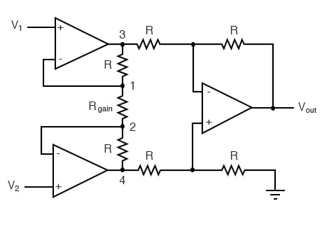
Since it's a instrumentation amplifier with 3 op amps, P1+R11 creating the "R Gain"
So as k brown suggested:
I think R11 to 470 ohms should do it.
Why not adding more resistance on R11 to reducing the amount of gain?

instrumentation-amplifier-circuits.jpg
 
If the circuitdiagram is correct, this is realy a very bad design. R4 and R6 should be 10 ohm max, not 10k and the input capacitors should be at least 47u each iso 1u. The opamp is also not suited for a mike preamplifier. It might more or less work for high output microphones, but is far too noisy for eg dynamic microphones.
 
And the phantom power is 21 volt according to the circuitdiagram. If true, the 6k8 resistors should be lower (approx 3k3). Otherwise this amplifier will not work with most microphones. Better to redesign the phantom supply to deliver 48 volt.
 
If the circuitdiagram is correct, this is realy a very bad design. R4 and R6 should be 10 ohm max, not 10k and the input capacitors should be at least 47u each iso 1u. The opamp is also not suited for a mike preamplifier. It might more or less work for high output microphones, but is far too noisy for eg dynamic microphones.

Well, the input impedance setting resistors are 100k, not the more usual sub-4k, so the capacitor values are fine (considering what "class" of device this is). I agree on the series input resistors though.

The OP's question regards lowering the minimum gain of the circuit, which no amount of messing with the gain adjustment pot will fix.

https://khronscave.blogspot.com/2019/10/55-focusrite-scarlett-2i2-teardown.html
A few years ago i did a similar mod on a friend's Scarlett 2i2 - scroll down to the last two photos in the post, and read those paragraphs there.

Although the feedback arrangement in this Rolls circuit looks a bit more complicated, so you might want to simulate that and fiddle with resistor values "virtually" first.
 
Last edited:
Well, the input impedance setting resistors are 100k, not the more usual sub-4k, so the capacitor values are fine (considering what "class" of device this is).

The OP's question regards lowering the minimum gain of the circuit, which no amount of messing with the gain adjustment pot will fix.

https://khronscave.blogspot.com/2019/10/55-focusrite-scarlett-2i2-teardown.html
A few years ago i did a similar mod on a friend's Scarlett 2i2 - scroll down to the last two photos in the post, and read those paragraphs there.

Although the feedback arrangement in this Rolls circuit looks a bit more complicated, so you might want to simulate that and fiddle with resistor values "virtually" first.

Well, The reason that input capacitors of microphone preamplifiers must be large has nothing to do with the input impedance of the amplifier, but with the noise current generated by the input stage of the amplifier itself (resistors and Rbb'of the input transistors ,discrete or from the opamp). This current flows BACK into the input capacitors and will cause input noise VOLTAGE over this capacitor. Since the source impedance of most microphones is only a few ohms (certainly the case with reasonable capacitor microphones) the inpedance of the input capacitors must be low at audio frequencies compaired to this and NOT compaired to the input impedance of the amplifier.

However the remainder of this amplifier is so badly designed, that this obvious design error will not influence the noise too much, given the fact that there is at least 2x10kohm resistor in series with the source. I really doubt if this is really the case. Are you sure that these resistors are really 10k?

The 4580 opamp has a noise voltage of approx 5 nV/root(Hz) which is at leat 5 times the amount of noise expected from a normal microphone pre amplifier (14dB more noise!!) Although the circuit in the photo's looks similar to that in the diagram above, it is a completely different beast when it comes to performance. The 2212 chip is in fact a pair of very low noise transistors and not an opamp.
 
Thank you all for your comments, I've ended up replacing R10 with 10K and R11 with 470R resistors.
With those values, the gain knob still makes effect.
Now the gain is low enough to work with the AKG C411 condenser without clipping.
The low voltage phantom is not an issue in this case since the C411 can work with a 9-52V phantom power.
The low quality of this preamp is not a big issue in this case since this preamp connects to a pedalboard with effects that runs on 9V supply.
The biggest advantage of this preamp (in this situation) is that it's working on a 9V supply with a reverse polarity (outside positive, inside negative) so it can work with a MXR brick power supply.
 
Back
Top