ruffrecords
Well-known member
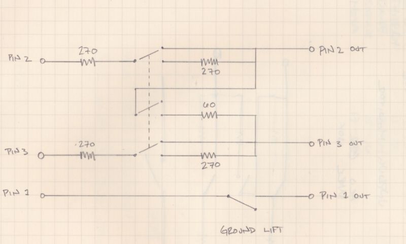
It is often necessary to have a 600 ohm load available when testing balanced outputs. Testing their maximum output into a 600 ohm load can also be a problem, especially if you are using something like RMAA and an ADC that will not cope with input levels of +20dBu or so. So I designed a simple switched attenuator that presents either a 600 ohm load or or provides a 20dB pad with a 600 ohm load simply by flicking a switch. All you need is half a dozen resistors, a couple of XLRs and a DPDT toggle switch. I built mine in a small die cast box holding the output XLR and the switch. The input XLR was on a flying lead so I can plug is straight into an output and plug my test gear into the die cast box. The schematic is attached.
In the 0dB position , R1 and R4 are shorted out so the input is connected directly to the output. R2, R3, R5 and R6 provide a 600 ohm balanced load. In the -20dB position, R2 and R5 are shorted out and R1 and R4 are in series with the input. These, with R3 and R6 provide a 20dB balanced attenuator and a 600 ohm load. What I like about the design is that it does not need any weird resistor values yet is provides exactly 600 ohms load and 20dB attenuation. The 30 ohm resistor I made from a pair of 15 ohms in series.
Cheers
Ian


![Electronics Soldering Iron Kit, [Upgraded] Soldering Iron 110V 90W LCD Digital Portable Soldering Kit 180-480℃(356-896℉), Welding Tool with ON/OFF Switch, Auto-sleep, Thermostatic Design](https://m.media-amazon.com/images/I/41gRDnlyfJS._SL500_.jpg)


