


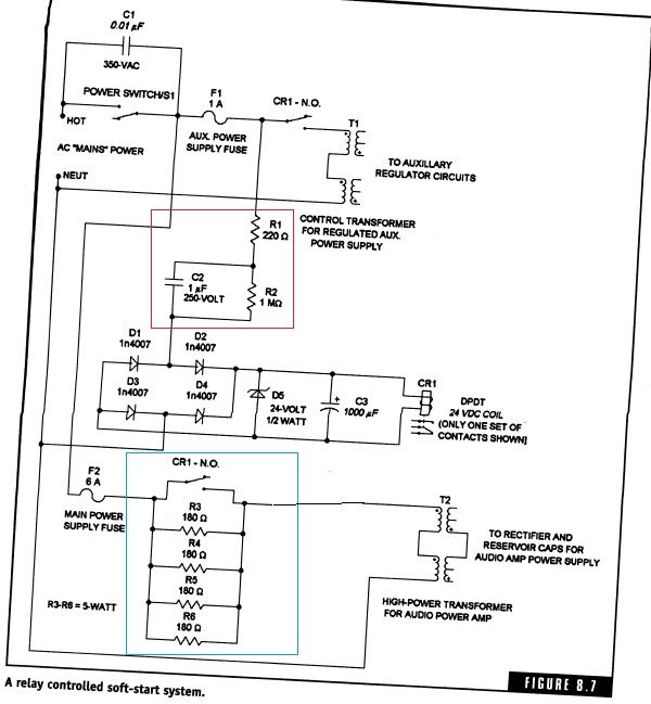
Can anybody provide input on the included schematic as a viable softstart circuit to use with an Avel Lindberg 1000VA (45V+45V) transformer. I'd like to make sure it's compatible with 120/240VAC. The design I'm considered and pictured in this post uses a DPDT relay network to delay the delivery of the full in-rush current (through power resistors) to my main (and secondary) transformers.
I move around and live both in the US and overseas so I wanted to mod an amp project I built over 10 years ago to work without buying a separate step-down transformer. Outside of increasing some of the voltage limits on the caps and the wattage ratings for some of the resistors and diodes I didn't know if there is something else I'm missing or should consider. I have to admit too that the part I outlined in red (RC network in series with another resister) I'm not totally sure why it's there. I got this design from one of Randy Slone's books.
If you want additional details on this here they are:
I've been researching the softstart issue for a while. As I mentioned I have books from Slone and three books from Doug Self. For the latter he has a little discussion on the topic, but not as in depth as I was hoping. I've looked at Bob Cordell's book as well, but haven't bought it and don't know what he has to say about in-rush issues/designs. I've also been searching the web for designs or something I could just buy. Probably the most useful info I could find was from Elliot Sound Products (ESP) at http://sound.westhost.com/project39.htm
I have a two channel amp I built over 10 years ago in college and it was a 100W x 2 implementation. However, it was designed to be 200W per channel. At the time I didn't want to spend the extra money to give the full power. Now I'm going back to implement the two additional output devices (L-MOSFETs) per channel and need to do a power-supply re-design to accommodate this. Before I was only using a Plitron 500VA transformer and have gotten by without any type of softstart circuit. Now I'm actually going to wire up a 1000VA (45V+45V) and 100VA (22V+22V) Avel Lindberg transformers. The main supply is center tapped and will have 40,000uF for filter capacitance each for the positive and negative rails. I'll also add that I have a power entry module (PEM) I picked up at Mouser that allows you to wire up the mains of my transformer for both 120 or 240 (parallel and series) and then switch between them.
The auxiliary circuit that will be using the 100VA center tapped transformer already has a rectification and filtering built-in to the board so I didn't really see trying to use the main transformer to power it as a convenient option. That circuit is used to accept a double ended balanced input (via XLRs) to single ended output that is output to the power amplifier circuitry.
If you focus your attention on the section I put a blue box around and if my calculations were correct from the info listed on the ESP website it says I should be using approximately three 90 ohm 10W resistors in parallel (30 ohms equivalent) when I'm running power at 240V. Then for 120V operation I should be using three 30 ohm 10W resistors in parallel (10 ohms equivalent). The calculated value was actually lower for that, but he recommended 10 ohms as a minimum. Is it worth it to run the two different resistor networks or will a compromise of some sort be sufficient. My 120V number is also obviously different than from what Slone calculated in the pictured schematic (45 ohms equivalent with a 5W rating for each one).
I know this is a long post, but thanks for any help or insight the community can provide.
I move around and live both in the US and overseas so I wanted to mod an amp project I built over 10 years ago to work without buying a separate step-down transformer. Outside of increasing some of the voltage limits on the caps and the wattage ratings for some of the resistors and diodes I didn't know if there is something else I'm missing or should consider. I have to admit too that the part I outlined in red (RC network in series with another resister) I'm not totally sure why it's there. I got this design from one of Randy Slone's books.

If you want additional details on this here they are:
I've been researching the softstart issue for a while. As I mentioned I have books from Slone and three books from Doug Self. For the latter he has a little discussion on the topic, but not as in depth as I was hoping. I've looked at Bob Cordell's book as well, but haven't bought it and don't know what he has to say about in-rush issues/designs. I've also been searching the web for designs or something I could just buy. Probably the most useful info I could find was from Elliot Sound Products (ESP) at http://sound.westhost.com/project39.htm
I have a two channel amp I built over 10 years ago in college and it was a 100W x 2 implementation. However, it was designed to be 200W per channel. At the time I didn't want to spend the extra money to give the full power. Now I'm going back to implement the two additional output devices (L-MOSFETs) per channel and need to do a power-supply re-design to accommodate this. Before I was only using a Plitron 500VA transformer and have gotten by without any type of softstart circuit. Now I'm actually going to wire up a 1000VA (45V+45V) and 100VA (22V+22V) Avel Lindberg transformers. The main supply is center tapped and will have 40,000uF for filter capacitance each for the positive and negative rails. I'll also add that I have a power entry module (PEM) I picked up at Mouser that allows you to wire up the mains of my transformer for both 120 or 240 (parallel and series) and then switch between them.
The auxiliary circuit that will be using the 100VA center tapped transformer already has a rectification and filtering built-in to the board so I didn't really see trying to use the main transformer to power it as a convenient option. That circuit is used to accept a double ended balanced input (via XLRs) to single ended output that is output to the power amplifier circuitry.
If you focus your attention on the section I put a blue box around and if my calculations were correct from the info listed on the ESP website it says I should be using approximately three 90 ohm 10W resistors in parallel (30 ohms equivalent) when I'm running power at 240V. Then for 120V operation I should be using three 30 ohm 10W resistors in parallel (10 ohms equivalent). The calculated value was actually lower for that, but he recommended 10 ohms as a minimum. Is it worth it to run the two different resistor networks or will a compromise of some sort be sufficient. My 120V number is also obviously different than from what Slone calculated in the pictured schematic (45 ohms equivalent with a 5W rating for each one).
I know this is a long post, but thanks for any help or insight the community can provide.