Solid state soft start for psu

GroupDIY Audio Forum

Help Support GroupDIY Audio Forum:

This site may earn a commission from merchant affiliate links, including eBay, Amazon, and others.
Now i'm playing again with transistors again to open a MOSFET.

The PNP transistor Q2 can never turn on in that circuit. For PNP to turn on the base must be more negative than the emitter, but in that circuit the base can only be in the range from same as emitter (0V) to +19.6V.
The base of Q1 is pulled positive by R2 immediately when power is applied, which causes the emitter to be 19V immediately.
 
A Schmidt trigger?

Again, you seem to be mixing delayed start with slow start. Once the output flips high, it will do so in nanoseconds, and instantly turn on the FET, just later.

You want something like a capacitance multiplier, fed from a mid-ish impedance so it actually ramps the rail output slowly (not later).


Well, i could also take CD4050 or and, not or so gate.
the input is hi impedance and doesn't mess with the RC capacitor and returns hi output of the total voltage.

Simulation shows once the mosfet opens only 2-3 Amps rush in rather than 1000+, the IRF4905, IRLZ44 can take this.
 
If you want to ramp up the voltage avoid using BJTs, use a single P-MOSFET, two resistors, and a capacitor.
Use a low RDSon FET.
 
A Schmidt trigger?

Again, you seem to be mixing delayed start with slow start. Once the output flips high, it will do so in nanoseconds, and instantly turn on the FET, just later.

You want something like a capacitance multiplier, fed from a mid-ish impedance so it actually ramps the rail output slowly (not later).


PSU - mosfet.jpeg
Falstad sim: https://tinyurl.com/2xvbj8yz

This seems to be reliable.

You definitely want more than 10000uF, than it caves in like 0.75 V with load.
25000uF, something like 0.6 V, but the voltage stays stable and, doesn't dance around with "music", the transformer doesn't have to work that hard. even the 1k can be 1 watt, rather than a monstrous big thing.
(shows the sim)

like this (5.6 uF) the supply of transformer would not exceed 1.5 amp, around that.
 
Last edited:
It doesn't need to, the gate is held at 0v. Since the source is connected to a negative supply the gate to source voltage will be positive, turning on the mosfet.
But that's my point: the FET will turn on the instant the source falls below the threshold of the FET, meaning there is no "soft start" as seen at the drain. The drain will go as fast as the supply feeding it.
 
The symbol is an N-channel. The circuit would not work with a P-channel.

indeed, have to be carefull and use them evenly, i have a matching or equal count of P & N channels.

I turned it around.
PSU - mosfet 2.jpeg

However according to the sim, it's not the same as before although using the same 82k resistor, 5.6 uF cap but with P channel, before it would suck like 1.5 Amps, now it tops at 450 mA and it takes longer to reach the voltage as the supply.
 
The final iteration.

PSU - MOSFET 4.jpeg

I gotta be careful with the source & drain when routing this pcb.
The P-channel on the positive rail is wired as you expect, but the N-channel negative rail would appear in reverse to the untrained eye.

I added a low pass filter (values not defined, yet) to filter out any "whistling" or so noise on the gate's.

To bad is not easy to add a latch.
 
p15_fig5.gif
 

That does not really address the inrush current into the 10,000uF capacitor. Why not put the MOSFET between the rectifier and the largest bulk capacitors? That way you reduce the inrush current through the rectifier and transformer as well as soft-start the voltage to the rest of the circuitry.
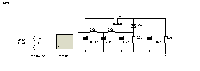
 
That does not really address the inrush current into the 10,000uF capacitor.
True, but it seems odd to go to all the effort, and add $10 worth of components and complexity in order to protect a $2 capacitor. :)

In my tube supplies, I have a similar soft-start as what I posted above, and the RC on the gate keeps the B+ under 68% of it's max until about 10 seconds after the heaters are energized. Heater inrush is controlled with an NTC on the primary (which tends to help all of the secondary rails simultaneously).
 
add $10 worth of components and complexity in order to protect a $2 capacitor.

If you add a soft start circuit then the components are already there, and should be well under $10. It is just a matter of re-arranging where the components are installed.
And that is not just to protect the capacitor (although it probably has that result), but to also reduce strain on the power transformer, the fuse, and reduce power line disturbances that might cause noise in other components.
 

Hey, these 2K2, 47uF low pass filters are rated for 0.0015392 Hz.
2 pole?

I choose for something close to <20 Hz using 22K and 390nF, does that matter?

I played around some more with the circuit as i received the diy class ab amp pcb in the mail today.
Aisler ingores top/bottom values and names layer, the changed something, no "text" on the pcb.

Added some totem pole to figure as mosfet driver, after i "accidentally" saw a guy talk about his project.
This is not the whole circuit, just the mosfet thing.

psu - mosfet5.jpeg

Somehow on the postive rail there is a spike of several amp after resetting simalation.
That's why the 10M resistor to see if it can be solved or is just a glitch.
 
Last edited:
It took me a while but the above circuit has glitch.
I had to move things around, the p-channel back to the negative supply and so.

The use of a "low pass filters".
2K2, 47uF (0.01 Hz) from:
https://groupdiy.com/threads/solid-state-soft-start-for-psu.87634/post-1152983
That's a very good idea, because i substituted the static voltage source with an 100Hz AC input (after bridge rectifier) with an offset. but you only get the average voltage, so it's needed to add a small 10uF or so in front of this circuit.

YouTube showed me some video on how to calculate capacitors in such applications, something with square root.
 
Last edited:
2K2 into 47uF has a pole at 1.5Hz. However two stages gives 40dB/decade, so at the gate of the MOSFET, your 120Hz (or 100Hz) ripple is over 80dB down, leaving a very clean output on the source of the MOSFET...in addition to the slow start behavior.

I use the exact same circuit in various tube amp projects for screen and preamp B+ supplies. With a high voltage MOSFET, it's very stable with a 1K gate resistor, and can even be made to withstand shorts or overcurrents (shorted output tubes, etc) with a simple current clamp. It's also easy to make a negative version for bias supplies by flipping everything upside down, and switching to a PMOS (since bias supplies generally don't need to provide much if any DC current, the PMOS can even be small like a TO-92).
 
Back
Top