Solidstate Idea

GroupDIY Audio Forum

Help Support GroupDIY Audio Forum:

This site may earn a commission from merchant affiliate links, including eBay, Amazon, and others.
[quote author="analag"]
http://www.dself.dsl.pipex.com/ampins/discrete/cfp.htm

It's in this article, I just used a single supply and tweaked it a little.

analag[/quote]

aha. Ive got great results starting at the same place. I like the combo of K170 FET and BD140.
 
[quote author="mikep"]aha. Ive got great results starting at the same place. I like the combo of K170 FET and BD140.[/quote]

Mike - I've been meaning to ask you; Do you mean the FET and the PNP together in a CFP configuration, or the FET as an input stage followed by the CFP output?
 
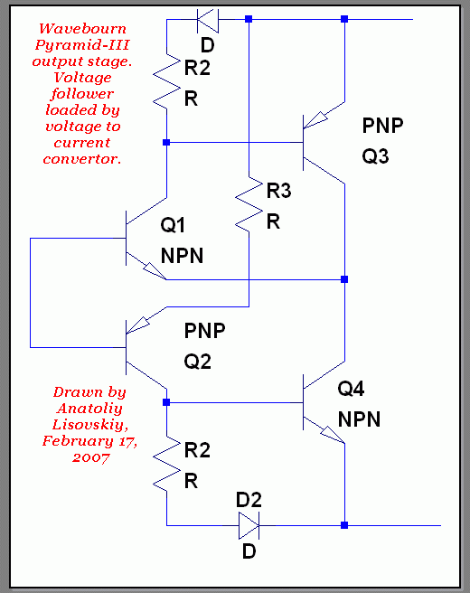
Mine is better:

pyramid-III.gif
 
[quote author="skipwave"][quote author="Wavebourn"]Mine is better:[/quote]

If you say so... :razz:[/quote]

Also, if you try and compare. :grin:
 
[quote author="skipwave"]Ok, you got me there, I'll have to try it to know either way. I just had to point out the hubris.[/quote]

I can explain: diodes with resistors improve linearity (current mirror); also loading follower on a voltage to current convertor rather than on a plain current source improves linearity and increases effectivity.
 
[quote author="Wavebourn"]Mine is better:

pyramid-III.gif
[/quote]

Good looking schematic... but better at what...?

It looks like a compound follower, which will need to stabilize the voltage gain of the common emitter stage and deal with PSR for that upper pnp. The lower npn is basically a current source that varies some with output voltage.

It might be more clever if the lower current source was modulated by output current instead of output voltage, but for a known, well defined resistive load that will work OK.

JR

PS: I think Panasonic or one of the Japanese audio companies patented a similar approach where the lower current source was modulated to make a more efficient class A amp... Sorry I don't have any specific references that was decades ago.
 
John, in my case current source is modulated by input signal, without additional phase shifts and non-linearities as in usual case of modulation by output signal (which you ironically call "more clever").

[quote author="JohnRoberts"][quote author="Wavebourn"]Mine is better:

[/quote]

Good looking schematic... but better at what...?

[/quote]

Better at being output voltage follower for audio. I use such approach everywhere where need a voltage follower: in tube mic pre, console, hybrid class A power amp (room heater).
 
We all think our children are cute and smart and our personal observations clever (mea culpa). :?:

For internal circuit nodes where you know the worst case loading, you can bias this adequately feed forward. While this topology will not exhibit any crossover distortion within it's output current range, the different current gain for positive and negative signal swing may introduce low order distortion components and asymmetrical current limiting. For negative signal swings you have R2/R3 times the transconductance of Q4, while for positive swings it's R2/R-emitter of Q1 times transconductance of Q3. While you haven't provided any values I will speculate that R3>> R-emitter. To the extent that R2/R3 x Q4 mimics the load current, you will get a first order linearization. For unmatched loads, either above or below target you will get distortion similar to a simpler follower.

A great deal of design effort has been invested in making a power amp output stage that never completely cuts off, or turns on again well before reaching the class B hand off between + and - stages to minimize device turn on artifacts. Any low order non-linearities generated by such approaches can be reduced using global negative feedback.

So for use in a controlled environment this may have merit (if you don't mind the extra complexity). I recall the difficulty in past console design efforts just trying to balance out signal current flows into and out of local PS and grounds, because of changing loads (like faders and pan pots for example) making it impossible to target a single fixed load for such a circuit. Use in output stages is similarly compromised.

JR
 
[quote author="JohnRoberts"]

For internal circuit nodes where you know the worst case loading, you can bias this adequately feed forward. While this topology will not exhibit any crossover distortion within it's output current range, the different current gain for positive and negative signal swing may introduce low order distortion components and asymmetrical current limiting. For negative signal swings you have R2/R3 times the transconductance of Q4, while for positive swings it's R2/R-emitter of Q1 times transconductance of Q3. While you haven't provided any values I will speculate that R3>> R-emitter. To the extent that R2/R3 x Q4 mimics the load current, you will get a first order linearization. For unmatched loads, either above or below target you will get distortion similar to a simpler follower.


JR[/quote]

It is right.

Now compare load by plain current source and get worse results; now compare load by a plain resistor and get even worse result.

I see what side you are pulling the blanket to: symmetrical voltage followers. No, no, and once more no. I do not want to shift distortions to higher order and lower volumes for meaningless measurement sake. I optimize for sound quality. Period. I know the whole industry goes such a way, like rams follows by leader. Let them go, I want my own way, and I hear results.
 
A very interesting discussion!
Perhaps Wavebourn could kindly provide values so fellow DIYers could build one and see how it sounds.

Sorr
 
[quote author="Sorr"]A very interesting discussion!
Perhaps Wavebourn could kindly provide values so fellow DIYers could build one and see how it sounds.

Sorr[/quote]

For +/-15V power and 600 Ohm output?

R3 defines current through 2'nd transistor, iddle current through 3'rd and 4'th transistors must be half of peak current on given load, so calculate R3 depending beta of the 4'th transistor (it amplifies current defined by 2'nd transistor).
 
I do not want to shift distortions to higher order and lower volumes for meaningless measurement sake.
Why should a complementary follower have more higher order distortion products? It has less even order for sure. Do you have any measurement results (or at least a sound theoretical explanation) to support your point of view?

Samuel
 
[quote author="Samuel Groner"] Do you have any measurement results (or at least a sound theoretical explanation) to support your point of view?
[/quote]

Yes, both. Also, audible results.
 
[quote author="Samuel Groner"]Then please post them...
[/quote]

No, not anymore. Tired.
 
FWIW this (Wavebourn's "Better") is an improved (more efficient) class A follower. In a classic class A the current source is DC biased at peak current, and follower device varies between 1x at idle to 2x at positive peak and 0 at negative peak.

This improved variant, uses 1/2 the class A bias current and now varies from 1/2 peak current at idle, to 1x current at positive peak to zero at negative peak. The follower device is only working half as hard, and heat losses will be lower, but distortion characteristic will be similar.

OTOH, if willing to trade some of that hard earned efficiency for less distortion adding back in some fixed DC bias to the variable bias in Q4 will reduce the range of current change in the follower. If a constant current, also equal to half peak was added to the dynamic current we would now have a follower that varies from 1/2 peak at peak minus to 1x at idle and 1.5x at positive peak (only 3:1 change).

If instead we trade some complexity to keep the improved efficiency, add a similar dynamic current loop to the other phase (add another NPN in parallel with Q1 but connect emitter to minus supply through a resistor the same value as R3. You still have the benefit of 1/2 idle class A current but now the current in the follower is zero at idle, zero at positive peak and zero at negative peak. Since followers need some forward bias, add a modest additional dc bias current into Q4. Now the follower will work constant current for low distortion.

With my apologies in advance to Wavebourn, I might suggest a small change to the modulated current sources. Adding a resistor R-em in series with the emitter of Q4 (and Q3) now allows the transconductance to be defined by simple resistor ratios. Setting the peak/2 idle current now becomes current in R3 times R2/R-em.

It is worth noting that there is a base-emitter voltage drop between input and output, and dynamic bias generators will be offset from midpoint between supplies, so rather than dialing them in for peak current/2 perhaps target 2x load resistance scaled also for R2/R-em ratio.

Caveat: I have not bread boarded any of these circuits, and don't plan to, so it might not even work, and if it does it might not have that classic class A sound (distorted). But it was more fun writing about this than chasing the bug in microcomputer firmware I should be working on.

JR
 
John, think of 2 modes for my output amp:

1. Hi-Fi mode. I0=Imax/2. High efficiency. I use it for power amps.
2. Hi-End mode. I0=IMax. A voltage follower is happy: it always sees the same emitter current. The minimal possible distortions, especially less on small signals. I use it for line drivers.

PS: how you implement current mirrors is not critical. Yes, transistors instead of diodes and resistors in emitters is better way for mass production.
 
Back
Top