Bo Deadly
Well-known member
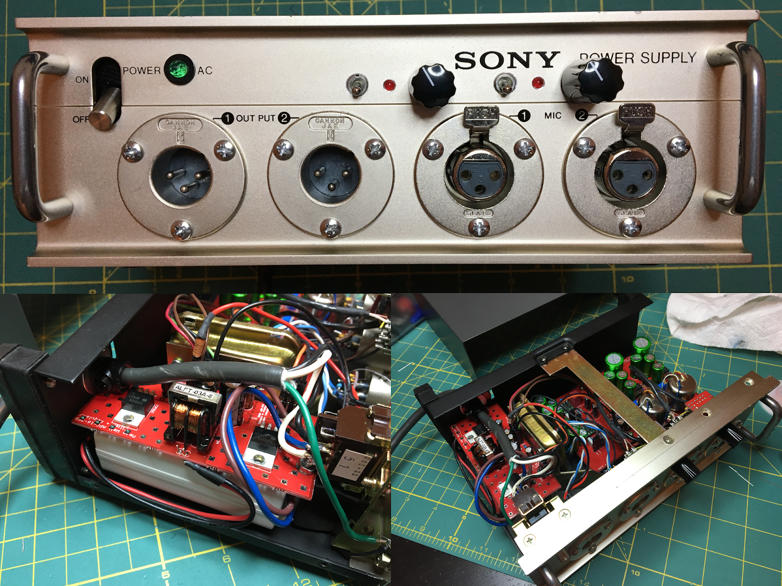
I just picked up one of these:
Sony AC-148F phantom power supply
The pics are not of mine but it's the same exact model near as I can tell. I'm reasoning that I could make a nice remote dual mic pre with it. It has a nice enclosure with all of the right connectors and space for more controls on the front, shielded bullet transformers, a shielded power transformer with 48V for phantom and hopefully enough juice for the amp circuits.
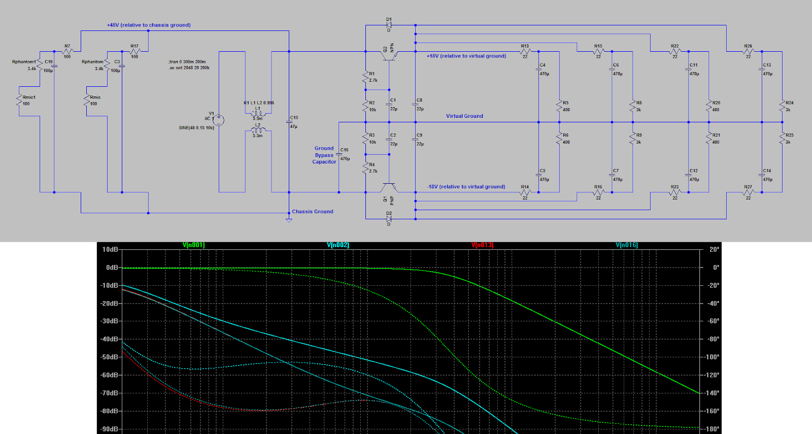
The question is, what circuit to put in? The single supply suggests something discrete but I could pretty easily make a virtual ground.
So what do you think? What should I do with this? Should I make a lot of fancy plans and then leave it in a closet and forget about it?
UPDATE:
Done. Created a PCB for a dual THAT 1510 / THAT 1646 with small SMPS supply. Switches are 3 pos and use a smaller cap in the gain control to integrate low-cut directly into the 1510 CFP. LEDs trigger on +17dBu. Works sweet.


![Electronics Soldering Iron Kit, [Upgraded] Soldering Iron 110V 90W LCD Digital Portable Soldering Kit 180-480℃(356-896℉), Welding Tool with ON/OFF Switch, Auto-sleep, Thermostatic Design](https://m.media-amazon.com/images/I/41gRDnlyfJS._SL500_.jpg)


