Sony C-38B Low Output

GroupDIY Audio Forum

Help Support GroupDIY Audio Forum:

This site may earn a commission from merchant affiliate links, including eBay, Amazon, and others.

smilan

Well-known member
Joined
May 29, 2017
Messages
467
Hi,
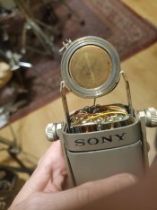
I have a faulty Sony C-38b condenser.
At the "M" mode the signal is very low and it's getting very low and then stronger from time to time.
In all the other modes there's a very weak signal with almost no low frequencies.
I replaced all the electrolytic caps on both boards and in the dc to dc converter.
I also replaced R1 since it measured as a capacitor instead of a resistor.
I took some voltage readings and it seems like some of the voltages are a little bit higher and some of them are a little bit lower than the schematic.
There's a way to determine if it's a case of a dead capsule or something with the electronics?
 

Attachments

  • c38b-5.jpg
    c38b-5.jpg
    1.6 MB · Views: 4
  • 321607357_493921496058152_2972275989192657000_n.jpg
    321607357_493921496058152_2972275989192657000_n.jpg
    224.5 KB · Views: 1
Thanks, the capsule seems to be good.

I have a Blue Baby Bottle so I tested the Blue capsule in the Sony and still had low output and connected the Sony capsule to the Blue mic and got plenty of output.
Do you have any suggestions on how to troubleshoot the electronics?
 
Last edited:
Have you checked the selector switch and connections? Maybe it could be a bad connection. I once worked on a LOMO and the low output was corrosion at the cable connectors.
Can you check it with a oscilloscope?
Do you have a signal generator?
It is a JFET BJT follower so the output should be close to the input signal.

You could have a low no voltage capsule charge voltage.
You posted it is more audible in M and that has the higher cap value to the transformer.
Or you could have a bad transformer.
Was it dropped?
If so check the pcbs for cracks and broken solder.
 
Have you checked the selector switch and connections?
The switch seems to work good, I tested it with continuity mode of the DMM and it beeps as it should.
Can you check it with a oscilloscope?
Do you have a signal generator?
Yes, I have both oscilloscope and a signal generator.
What exactly should I check?
You could have a low no voltage capsule charge voltage.
How can I test it? What should be the capsule charge voltage?
You posted it is more audible in M and that has the higher cap value to the transformer.
Or you could have a bad transformer.
Maybe it's the transformer, the dc resistance between the Yellow wire to ground is 2.7K.
Blue to White: 46.5 Ohm
White to Black: 46.5 Ohm

Was it dropped?
If so check the pcbs for cracks and broken solder.
I bought it second hand, it might dropped in the past, but not since I have it.
 
Can you check it with a oscilloscope?
Do you have a signal generator?
It is a JFET BJT follower so the output should be close to the input signal.
When I'm injecting an audio signal to base of Q1 there's an output signal with level that is close to the input signal.
So if the capsule is working on another mic, and the amplifier is working the only thing that causing this issue is the dc to dc converter that seems to fail to charge the capsule with the right voltage?
What should be the voltage of the capsule?
Any idea how to test it / how to build an equivalent circuit that will charge the capsule with the right voltage?
 
the only thing that causing this issue is the dc to dc converter that seems to fail to charge the capsule with the right voltage?

Can you take photos of the DC to DC converter?
Is it an encapsulated module or an open discreet circuit?

Best way to test it is to know what voltage it needs to see at the input and what voltage it should output

What should be the voltage of the capsule?

I would guess something between 30V to 60V
 
Can you take photos of the DC to DC converter?
Is it an encapsulated module or an open discreet circuit?

Best way to test it is to know what voltage it needs to see at the input and what voltage it should output


I would guess something between 30V to 60V
Here are some photos, I also found a schematic of the dc to dc converter of the C37fet.
When I connected it to an external PSU and fed it with 9VDC I measured at the output -1.7VDC
 

Attachments

  • c37fet-27.jpg
    c37fet-27.jpg
    419.3 KB · Views: 4
  • 321879245_1547651172413838_4394784306191215649_n (1).jpg
    321879245_1547651172413838_4394784306191215649_n (1).jpg
    210.8 KB · Views: 4
  • 321879245_1547651172413838_4394784306191215649_n.jpg
    321879245_1547651172413838_4394784306191215649_n.jpg
    210.8 KB · Views: 1
What are those components marked 207?
They are connected in series between the anode of the diode to the output.
In the middle there is a 0.001uF cap to ground.
While testing them with my LCR meter one tested 85uF and the other 135uF.
 

Attachments

  • 321522718_688973669443940_3992003062411031632_n.jpg
    321522718_688973669443940_3992003062411031632_n.jpg
    373.6 KB · Views: 2
When I connected it to an external PSU and fed it with 9VDC I measured at the output -1.7VDC

It seems you might have a shot DC converter.
There's a lot of DC converter modules that you can buy and probably replace that one, the problem is that you need to know what is the supposed output voltage.

Read this thread, there's some useful info on common fails with these mics,
you can also try to contact some of the knowledgeable people in the thread for help and more info:
https://gearspace.com/board/so-much-gear-so-little-time/748562-sony-c38-repair-where-can-i-send.html
 
Might not be the same circuit, you have to trace your DC converter to see if it matches that schematic or not.
I did it, it is not the same but it's quite similar.
I don't know if the coils values are right.
Schematic_dc to dc converter_2022-12-26.jpg
It seems you might have a shot DC converter.
There's a lot of DC converter modules that you can buy and probably replace that one, the problem is that you need to know what is the supposed output voltage.
Can I connect an external PSU to the capsule and turn the voltage up until the mic will work fine to determine the right capsule supply voltage? Or I might to do more damaged?
Read this thread, there's some useful info on common fails with these mics,
you can also try to contact some of the knowledgeable people in the thread for help and more info:
https://gearspace.com/board/so-much-gear-so-little-time/748562-sony-c38-repair-where-can-i-send.html
Thanks, I'll do that.
 
At the service manual of the C37fet I found this explanation about the capsule voltage:

5.4 Polarizing Circuit (See Figure 8). DC polarizing voltage applied to C-3 capsule is produced by stepping up 9V to 140V by an extremely small-size DC-DC converter. See attached Figure 8 for the circuit diagram. Voltage of very low frequency pulse wave-form of approximately 20 c/s is rectified and the ripple is eliminated by a large time constant filter circuit. This circuit provides a very stable DC voltage. The converter circuit is housed in an electro-magnetic shield case and located in the bottom of the case so as to be separated from the F.E.T. circuit. (Note: the polarizing voltage cannot be measured by an ordinary voltmeter or VTVM.)

The manual states that the polarizing voltage cannot be measured by an ordinary voltmeter or VTVM, so how it's possible to check this circuit?
 
Can I connect an external PSU to the capsule and turn the voltage up until the mic will work fine to determine the right capsule supply voltage? Or I might to do more damaged?

I think that’s risky, I wouldn’t do that and I don’t advise you to do that.

Maybe someone more knowledgeable than me can chime in.

In the gearslutz thread I posted I think someone mentioned the coils in the DC converter might fail. So maybe you can test them and see
 
The manual states that the polarizing voltage cannot be measured by an ordinary voltmeter or VTVM, so how it's possible to check this circuit?

True, you can't measure that reliably right at the output, but you could measure it across C5, assuming you have access to that.

Or actually, is the resistor before that, 1k, or 200meg?
 
At the service manual of the C37fet I found this explanation about the capsule voltage:

5.4 Polarizing Circuit (See Figure 8). DC polarizing voltage applied to C-3 capsule is produced by stepping up 9V to 140V by an extremely small-size DC-DC converter.

I’m quite surprise that the output voltage is so high.
I don’t think I’ve ever seen an LDC capsule polarised with such an high voltage.
I’ve only seen such high voltage in LDC mics when they’re tube based and only for the HT plate voltage of the tube, but not as polarization voltage
The manual states that the polarizing voltage cannot be measured by an ordinary voltmeter or VTVM, so how it's possible to check this circuit?

Yes, you have a 200Meg resistor at the output of the DC converter so you would need a very high input impedance DMM.

You can still measure it approximately by doing some math.
Imagine your DMM input impedance is 10 Meg ( my Fluke is, you have to see the specs of yours), and you have a 200Meg resistor.
It will form a voltage divider with the DMM of 10/200=1/20.

So if you measure 2 Volts with your DMM it will be actually 2x20v= 40v
5volts would be (5x20) = 100v
Approximately…

Read this thread as it’s better explained over there, check what CJ wrote and also others, very informative

https://groupdiy.com/threads/neumann-u67-repair-low-end-loss-help-needed.62582/
 
Good news, the microphone is working great!
I've been running it over two hours recording the same song and the output signal is steady.
There was a problem with the trimmer of the dc to dc converter.
After replacing it with a 56R fixed resistor the mic seems to be working fine with decent output and no voltage drops.
I found this post:
https://groupdiy.com/threads/sony-c37-fet-repair.60491/and realized that the transformer is in good shape after measuring pretty close DC resistance values.
I measured the voltage of the dc to dc converter using the null voltage measurement method.
I disconnected the converter output from the mic, then connected it to an external PSU and connected my DMM between the two voltage sources and raised the external PSU voltage until getting about 0V at the DMM.
The voltage of the converter depended on the trim pot but at about 3/4 the voltage was around 60V.
Thank you all for your help.
 
Last edited:

Latest posts

Back
Top