Soundcraft Series One * Legacy Console * Any Info?

GroupDIY Audio Forum

Help Support GroupDIY Audio Forum:

This site may earn a commission from merchant affiliate links, including eBay, Amazon, and others.

L´Andratté

Well-known member
Joined
Jan 17, 2013
Messages
804
Location
Hamburg Germany
So I recently acquired six channels from the first mixing desk Soundcraft ever did, Series One, it was conceived as live mixer, 16 into 4, came in a flightcase, with a lot of customisation possibilities. Lee Perry was rumoured to have used one in his Black Ark Studio, that got my interest. Although I´m not longer sure that was the case (I´m more of a King Tubby kind of guy anyways), I got further intrigued by what  little evidence and hearsay is to be found on the internet about this console:

1. It is a completely discrete design, no opamps, preamps are classA

2. Transformer balanced in (Sowter 4165, 1:7, no more info about that yet)

3. The circuit is very minimalistic, the pcb laid out clear and easy to understand, maintain and modify, there are equivalent options for the obsolete transistors used (2SC1681)

4. All over the web in obscure postings, people tell it did sound really good, the eq is four fixed bands with supposedly very good frequency selection

5. I found six channels of it for a moderate price (EU20 each including the transformer, fader, knobs and pcb, but excluding front panel, it was not a modular console). All this doesn´t seem to have seen much use and wear

So now I´m looking at getting the channels back to work (electrolytics, maybe transistors), building a power supply (+40V/0V/+48V), getting a well shielded housing for the preamps, doing some channel mods I deem necessary, and last but not least, build the master/monitor section and metering from the schematics, just because I can. Well, we´ll see...

I´m doing this for learning and because this old console is so inspiring, I know it won´t be Neve or Calrec preamps, a 5$ THAT preamp will probably be much cleaner and that´s totally fine with me.

It will be a long process, so this shall be my, you know, "build log" and I appreciate anyone sharing any information on the subject, helping to find answers to the questions that will definitly arise (a few have already arisen ;D) or just shows interest in this.

So how was that for an introduction? See you!

Schematics:
https://groupdiy.com/index.php?topic=44786.msg823946#new

Obscure service manual:
https://www.gearslutz.com/board/4460504-post14.html
 
They are fun little modules, I had a pair that I racked many years ago.  I sold them to an engineer who was going to be doing some work with Lee Scratch Perry and wanted to surprise him.  Never heard how that went...

Anyhow, the circuit is simple enough and with some fresh electrolytics it sounds decent.  Never heard a complete console so I can't say if it is worth building the master/monitor section.  Either way, enjoy them!
 
The mic preamps can be very clean, the combination of a good transformer and a well-otimized BJT stage being capable of excellent noise performance. However, the topology with a constant high-gain stage preceded by an potentiometer results in mitigated performance, particularly the noise level at less than maximum gain, which is constant -in fact worse at about 6dB below max.
That should not be a worry if you intend to rack them and use them in conjunction with a DAW.
What is a worry IMO is if you want to integrate them in a mixer, you'll be faced with the problem of operating level.
Due to the lack of post-fade buffer, the bus operate at -22dBu, i.e. 20dB below the most common "modern" operating level, making the summing amp noise an issue. With a small-format mixer intended for live applications (typically less than 24 stems), this is acceptable, but you may find that a limiting factor for other more demanding applications.
 
Thanks for the encouraging infos!

mjrippe said:
They are fun little modules, I had a pair that I racked many years ago.  I sold them to an engineer who was going to be doing some work with Lee Scratch Perry and wanted to surprise him.  Never heard how that went...
Scratch probably buried him in the backyard of Black Ark alongside his old console... :eek:

gar381 said:
These are WONDERFUL sounding simple desks. :)
Exactly what I had hoped to hear!

abbey road d enfer said:
..., the topology with a constant high-gain stage preceded by an potentiometer results in mitigated performance,...
..., you'll be faced with the problem of operating level.
Due to the lack of post-fade buffer, the bus operate at -22dBu,...
These are some of the things I was worrying about.

- Nominal operating level: yes, I want to mainly use the preamps into A/D, but also like this to be a
little standalone mixer and want it work as optimal as possible for me. As I´ll do the boards beyond the preamps myself I´m not averse to little mods if they substantially improve the circuit (->post fade buffer).
I just want to keep it in vein with the original design.
Abbey road d enfer, how do you arrive at -22dB (if you care to elaborae. Sorry, I´m not a professional just a
silly hack)

-I´d like to make the gain adjustable. At least a little bit to use with the input pot.
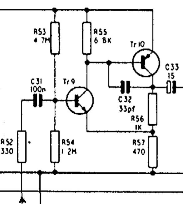
Unfortunatly in my limited understanding of transistor circuits, the only place to do this without fxxking up the topology, is C4 which shunts AC neg. feedback to 0V. If it is removed from the circuit (by switch), or if a small resistance is put between C4 and 0V gain should go down. At least in a world after my taste ;D
I´ll try that.

-Btw. shouldn´t there be a Zobel at the input? Gotta test the transformers.

-Then there´s the output amplifier driving fader+pan (r/l), foldback, echo, monitor AND the second eq network. And now I want to add also direct outs. Isn´t that a little much for humble Tr6? I mean those Soundcraft guys probably knew what they were doing, but the load must be down to a couple of k? Pre Fade buffer?

-R8/R3 (33k/12k) in the input drop the +V to about 10V. Why?

-Is there any benefit to NOT regulate the +V line?

That´s it for today...
 
You could add the fader buffer from the Soundcraft series two mixer if you want to
stick with the 40v supply and transistor design... should give another 10db of gain,
but not that much more low z drive.


There is some thougts around changing the gain of the pre amp here...
some posts down:
https://groupdiy.com/index.php?topic=46421.msg582461#msg582461

I try to refurbish a old series two mixer these days, and I dont look forward to test all the old pots and switches !!!:)
 
L´Andratté said:
Abbey road d enfer, how do you arrive at -22dB
6dB gain in the summing amp and 21 dB in the output amp, result in -23 dBu for +4dBu output.


-I´d like to make the gain adjustable. At least a little bit to use with the input pot.
Unfortunatly in my limited understanding of transistor circuits, the only place to do this without fxxking up the topology, is C4 which shunts AC neg. feedback to 0V. If it is removed from the circuit (by switch), or if a small resistance is put between C4 and 0V gain should go down. At least in a world after my taste ;D
I´ll try that.
I don't think it would change much because the main NFB loop is R10/R4.Increasing R4 would decrease gain with it would also play havoc with the operating point. You may try replacing R4 with a 50k potentiometer in series with a 4.7k; that would give you a range of adjustment of about 15 dB, provided it doesn't crete stability issues.


-Btw. shouldn´t there be a Zobel at the input? Gotta test the transformers.
Some xfmr's don't really need a Zobel, but in fact I think the designer chose to ignore the issue on account of relative inaudibility in the context of period PA systems.


-Then there´s the output amplifier driving fader+pan (r/l), foldback, echo, monitor AND the second eq network. And now I want to add also direct outs. Isn´t that a little much for humble Tr6? I mean those Soundcraft guys probably knew what they were doing, but the load must be down to a couple of k? Pre Fade buffer?
A post-fade buffer is almost inevitable if you want to create direct outputs.

-R8/R3 (33k/12k) in the input drop the +V to about 10V. Why?
That's a way of reducing the operating current in the input device, in order to optimize noise, and also providing extra filtering of supply noise.

-Is there any benefit to NOT regulate the +V line?
Voltage regulators can be problematic some times, like injecting noise current in the ground connection. And there are not much benefits. And less parts is less maintenance!
 
Ok, thanks to abbey road d enfer, now I have rough picture of how the amplifiers work, how their gain is calculated and how this corresponds to the nominal operating level.

I now see the problems with this design. Still I want to go on with this. Six preamps with small monitor and stereo master section. First with stock circuits, probably with post fader buffers, then modify if needed.

Today the boards arrived, I was pleasently surprised, not only are all six channels in very good condition, I´d say barely used, the seller also included two extra channels (without the transformers of course). This is very welcome now I have spare transistors (most of them will be fine anyway, I THINK :p).
But also he included the original headphone out/meter amp/monitor sum board and the foldback/eq/output board (two more of this will be needed for l/r master out). Very nice surprise. And the faders are actually decent, not high end in any way, but clean, vertical, smooth faders and the sowters just  :)

- So first I will restore the channels: axial electrolytic caps new, testing other caps/resistors/transistors/pots and transformers (zobel?) . Btw. did I mention, the boards are nice and no trace of grime anywhere?

- Then fight the cold and lonely struggle to order the right parts for the power supply

- Metalstuff and physical design will be a chapter on its own

Joechris, how could I overlook that thread. Thanks! I will try the mods from Balijon to get the gain down in the input amp.

Balijon said:
The Input Transformers in the Series-Two are 'higher quality' Sowters than in the Series-One. The earliest Series-One transformers (non-PCB-mounted) are the best. They have the same 1:7 ratio as the Series-Two.
I think I have the latter 6145 with mounting grommet!

Series two is also looking very interesting.

 
abbey road d enfer said:
6dB gain in the summing amp and 21 dB in the output amp, result in -23 dBu for +4dBu output.

-Still thinking about this. So the gain in the output amp has to go.
The mic amp has already enough gain (in fact I´m trying to find a way to bring it down).

-Concerning a real gain control in the mic amp, how about connecting an
additional fb-loop from behind the output capacitor to before input cap via pot, like seen here in this schematic?
http://sound.whsites.net/project13.htm
 
L´Andratté said:
-Still thinking about this. So the gain in the output amp has to go.
The mic amp has already enough gain (in fact I´m trying to find a way to bring it down).

-Concerning a real gain control in the mic amp, how about connecting an
additional fb-loop from behind the output capacitor to before input cap via pot, like seen here in this schematic?
http://sound.whsites.net/project13.htm
I don't know how this can be qualified as Low-Noise...
The 1.2k resistor at the input, actually in series with the source, increases the Johnson noise of the mic by 8dB.
Read my earlier post "You may try replacing R4 with a 50k potentiometer in series with a 4.7k;" That would be a much better solution.
Increasing the range of adjustment implies replacing R4 with a much higher value, which in turn forces resetting the operating point, and probably facing stability issues, which are not difficult to solve for an EE, but doesn't seem appropriate for you.
 
Very interesting thread to me.  I'm wondering if my Soundcraft Series 1s  (all recapped) has the same design shortfalls, like the same gain staging for instance?  It surely is more noisy than I would expect on the bus outputs.  I've uploaded the schemes to the tech docs ...  Thanks for any thoughts.

  https://groupdiy.com/index.php?topic=44786.0  (scanned by Brian Roth)

Edit:  After looking at the above  linked pdf  I found that the input Transformerless channels are different than my console. The inputs channels I have are TL072 IC  (no transistors) and utilize input transformers. The monitor outputs, echo returns and the output cards are identical though.
Also after reading this thread  https://groupdiy.com/index.php?topic=46421.msg582461#msg582461  linked earlier here by Joechris I own a console of similar problems and  also lower quality transformers.
 
Thanks for the feedback!

abbey road d enfer
I´m afraid, it couldn´t be worse from an EE standpoint, I actually  earn (part of) my money as a portrait painter, but a little motivation can take you a long way  ;)

hitchhiker
Strange, series 1 seems closer related to series 2 than to series 1s, which is more like later soundcraft mixers (differential input into op amp, wein bridge eq).
Check the output amps r/l for too much gain. Also are the channels grounded in series (ciletti)?

Whoops
No matter which of the three models you relate to, yes!
I´d like to know how much of these were built in their days.

 
L´Andratté said:
abbey road d enfer
I´m afraid, it couldn´t be worse from an EE standpoint, I actually  earn (part of) my money as a portrait painter, but a little motivation can take you a long way  ;)
I didn't write it to diss you, but for warning you that you're facing a very steep learning curve.  :)

hitchhiker
Strange, series 1 seems closer related to series 2 than to series 1s, which is more like later soundcraft mixers (differential input into op amp, wein bridge eq).
That is true; the Series II came as a more upmarket line, but still relying on the same building blocks than the series I.
Series Is came later, when technology advances and pressure from competition pushed Soundcratf to implement new solutions (transless mic pre, IC's vs. discrete) that were put to use in all the line (400, 800).
 
Joechris said:
Abbey, do you think the series 2 output amp could drive a 1:1 transformer?
I beieve you mean a 600:600 xfmr, because it can certainly drive a 10k:10k... ;)
It can drive a 600r load, although the 15uF output capacitor is a tad small, resulting in -3dB @20Hz.
Inserting a xfmr will result in a heavy LF hump, so you need to increase (about 20x) the capacitor value. Beware that some cheaper xfmrs have a quite low intrinsic inductance, which would result in significant LF hump and LF distortion.
 
The 22K+22K suggests a large-signal output impedance like 44K/hFE, maybe 400 Ohms.

It will "drive". It may not DRIVE huge signals in true 600r, or deep-bass in a small "600" transformer.

I would think multiple 10K loads, not 600.
 
PRR said:
The 22K+22K suggests a large-signal output impedance like 44K/hFE, maybe 400 Ohms.

It will "drive". It may not DRIVE huge signals in true 600r, or deep-bass in a small "600" transformer.

I would think multiple 10K loads, not 600.
That's what I thought originally, after a brief look, but note just how it is bootstrapped, so current capability on positive peaks is 500uA multiplied by hfe or about 50mA with only hfe=100.
I sim'd the circuit with LTspice, and it shows full 35V p-to-p into 600r with 40V B+ (including ca. 5% loss in the xfmr).
 
> I sim'd the circuit

OK, we are in a grey-zone where we can both be right.

I say if brought to near-clipped Sine with full load and *held* there, for a Second, C14 will discharge to some lower voltage. R27 current is less. Output drive is less. Output sags. Initially clipping on the + peak. Probably re-adjusting the center-voltage as time goes on.

There is a page on the topic in Power Integrated Circuits:... Antognetti.

Of course we ask: is sustained full-power Sine a fair test? We do it on Loudspeaker Amplifiers, where we have paid a lot for power and want to know if there is any short-fall on worst-case signals. A mixer should not be working to steady clipping, and will rarely see sines.
 
PRR said:
... if brought to near-clipped Sine with full load and *held* there, for a Second, C14 will discharge to some lower voltage.
Of course, we know that bootstrapping doesn't work at DC. But as long as the TC is long enough compared to the period of the lowest frequency to be passed, there is no issue there. The presence of input and output caps clearly shows no intention of passing DC.
 

Latest posts

Back
Top