helterbelter
Well-known member
Update :
The mods for turning a 552 into a summingbuscompressor are described in this updated first post : Scroll down for the "htdiy"
(how to do it yourself)
----------------------------------------------------------------
Hi there,
I've got quite a lot of emails recently with questions how to wire the SSL SL552 IMO module, so I've decided to start a new thread for this.
First, let's tell what a 552 IMO actually is !
IMO stands for Independant Main Output. Basically, it's this :
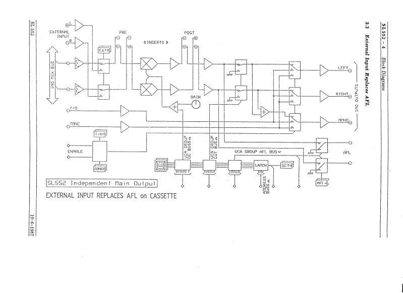
stereo summing amp > balanced inserts> masterVCA> balanced inserts> balanced output. There are a few more bells and whistles, but not interesting enough to take into consideration for building a summingbox.
Regarding the summingamp : it uses MAT02 as summingfront end and is completely identical to summingstage as the SL557 module which is the masterbus of the 5000 broadcast console.
(a sidenote: SL557F is a 5000 Filmconsole module, which doesn't handle audio).
Here's the block diagram. Ignore the external input, TB input, and everything below that. It's of no use (although the external input can be of use).
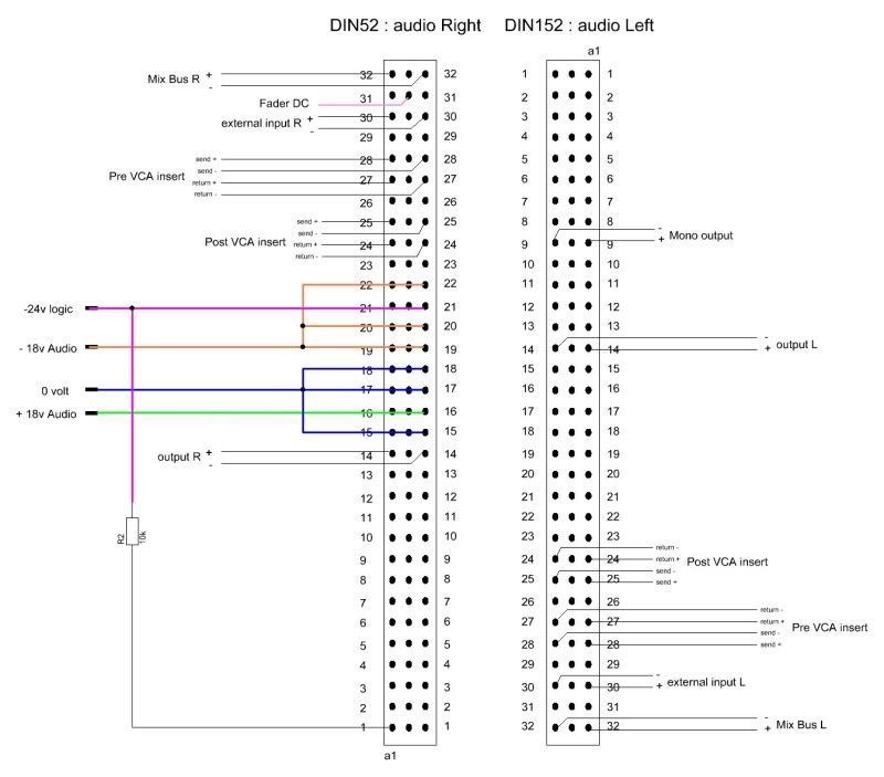
Here's the pinout diagram. The last stage is used solely for adding the talkback and tone inputs to the signal, so, you can discard that for the standalone racking : Simply use the post vca sends as outputs.
In case you want to use the last stage : The postvca insert can be jumpered on the DIN41612 using common jumperblocks as used in computers. a drop of soldering will do the trick as well.
The connectors you need for this are 2x DIN41612 sockets (not plugs!), 96 pin ABC, or 64pin A+C.
This is a way to make a passive summing resistor network that will work with these modules. Note that it's be best to use low tolerance metalfilm resistors, or handmatch them in sets of four. SSL usually uses 0.1% tolerance for the audiocircuits (although they don't use passive summingnetworks in their designs). Connect all the ground/sleeves of the inputs to the ground of the SSL module.
One thing that has to be noted : This summingnetwork is something I found in the SSL docs, as an alternative for the standard active summing that’s used in the 5K console. However, together with the summingstage of the 552 this gives a boost of 6 dB. Kante and I have experimented with shunt resistors, but it’s not possible to get it right with only a shunt. (Increasing the 10K resistors to, say, 20K, should be an option though).
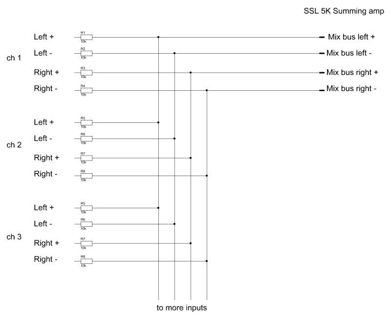
In case you have a few unbalanced lines that you want to add to the summingnetwork, it'd be best to wire the ground/sleeve of the output to the negative rail, and the plus to the positive rail (both via a 10k resistor of course). Don't connect the ground of the output to the ground of the summingnetwork.
Another good option, is to use the NYD design passive summing network. It’s somewhere here on the groupdiy site, so, hit the search button !
Udo is currently building a NYD summingnetwork, check this : SSL 552 Summing Box
PSU :
Regarding the PSU for SSL5k modules : I recommend the JLM audio 5 rail powerstation kits. a dual 18vac torroid in front will give you the desired voltages via the standard regulators.
If you're building a PSU solely for the 552, you could also use the 3 rail psu, and reverse the doubler rail into a negative doubler rail : You should reverse the caps and the diodes in the doubler circuit (including the chargepumpcaps), and use a 337 instead of a 317. This way a dual 15VAC torroid will do the trick. Note that the pinout of a 337 is different than the 317, so you should wire this one offboard.
EDIT : post from mrclunk and SSLTech :
Oh, and before I forget !
Keep in mind that the amp produces heat, so, make sure that there's enough space inside the box.
so here it is. I hope you all like this project, and goodluck building yours !
---------------------------------------------------------------------------------------------------------------------------------
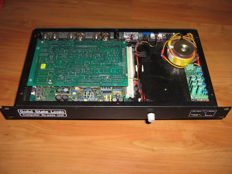
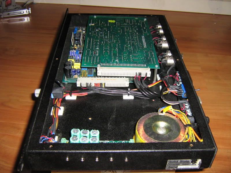
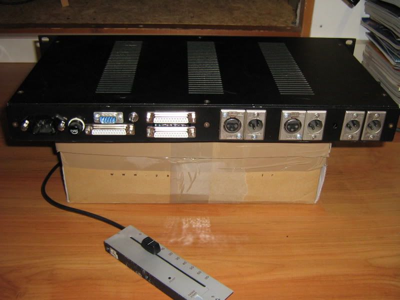
here are a few pics again of the 12 stereo input unit that I built a few years ago. Not that supergood looking, I know, but the wiring is done decently, and its sound is simply great. The summingresistor network is soldered directly on the sub-d inputs.
(btw, I haven't got this unit anymore, simply because I have built a bigger one, with 3 subgroups and active summing. )
……………………………………………………………………………………………………………………………………………………
Edit 24-11-11 :
Here's my recently finished SSL Summing Station Lunchbox :
http://www.groupdiy.com/index.php?topic=43999.msg585977#msg585977
Edit 1 Februari 2012 :
Here’s the necessary info for turning the 552 into a serious GSSL
Simply, by adding the GSSL sidechain stuff to the IMO’s VCA’s. This is even more simple than building a GSSL.
With this setup, you have an all complete SSL audiopath, with original SSL balancing and debalancing chips, paired temperature compensated DBX/THAT VCA’s for each channel, and of course the SSL summing stage as a luxurious bonus. (which you don't necessarily have to use : You can enter the VCA stage at the pre-vca insert return, thus bypassing the summing circuitry, so you can use it as standalone compressor also !)
What to do, is tapping off the audio signal in front of the VCA’s of the 552, route that to the sidechain circuit of a GSSL, take out the CV from the GSSL, and wire that to the 552 again. Wickedly simple !
Here the schematic and layout with the notes.
The 552 (just one channel shown by the way).

The modifications :
On both boards (85052 and 85152) :
-Remove the 2 resistors marked red . (R40 and R62) (edit : R40 doesn't need to be removed)
-Tap off the audio signal at point 3. (use the pad of the just removed resistor R62 that’s connected to RV5). This goes to the 47K resistors of the GSSL board (shown below in the GSSL board layout).
- Lift leg 3 of IC5, so it’s disconnected from 0v. The CV comes in at this point, so, solder a wire to it, and connect this to point 4 shown below in the GSSL boardlayout.
The GSSL board :
Only the components needed are shown here. Plus the gain make up pot of course !
A few notes :
-the 0v connection is not shown, but of course, it’s needed also. I don’t need to tell where to connect this, right ?
-Jumper the 2 resistors marked “2”.
-Replace the 2 resistors marked “1” with 4K7 resistors.
3 is where the audio left and right come in from the 552 boards,
4 is where the CV comes from, that go to the IC5 opamps on both 552 boards.

I guess that covers it……..
Of course, you can add the Turbo board from Expat to it, which is recommended , and also the SSC boards can be used with it. The wiring procedure for adding these boards, are the same as it would be for the normal GSSL.
Here a few pictures of the experiment. More to come !:


----------------------------------------------------------------------------------------------------------------------------------------------------------
Addition april 15th 2013 :
I've got some additional info : It's possible to power the 552 from the GSSL board.
The post VCA send will be the output of the module.
The following things will be removed :
the external input, and the post VCA circuitry including tone and TB insert, and mono output.
There are just a few simple things that need to be done to the 552 boards , then it's possible to take out the logic part, so you won't be needing the -25v line anymore.
That means, that you can use the GSSL +/-15 volt PSU part for powering the 552 module, by changing the 7815 and 7915 to 7818 and 7918 (and use a transformer with a dual 18v secondary.)
Here's how to do it :
The mods must be made on both boards.
Summing stage :
-remove TR1, TR3, TR7, and TR9.
-remove TR2 and TR4, jumper source to drain. (pins 2 and 1).
That’s easy, huh ?
Stuff that’s not in use, best is to take them out to reduce powerconsumption. Except for a few hybrid chips, all are socketed:
T85052 board :
Hybrid chips : H6, H7, H8 , H9, H10, H11, H12
Demux chips : IC 7, 8,9,10,11,12,13, 14, 17,
Plus on the T85152 board :
Audio chips : IC 7,8,9, 15, 16
Hybrid chips : H6, H7, H8, H9, H10, H11, H12 (H7 and H10 are soldered, you don't necessarily have to take them out).
Logic chips : IC 10, 11, 12, 13, 14.
The audiobalancing chips are valuable, so, keep them as spare. (85501 and 85502). The other hybrids are practically worthless.
------------------------------------------------------------------------------------------------------------------------------------------------------
Addition June 26th 2013 :
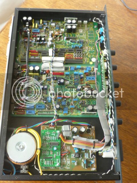
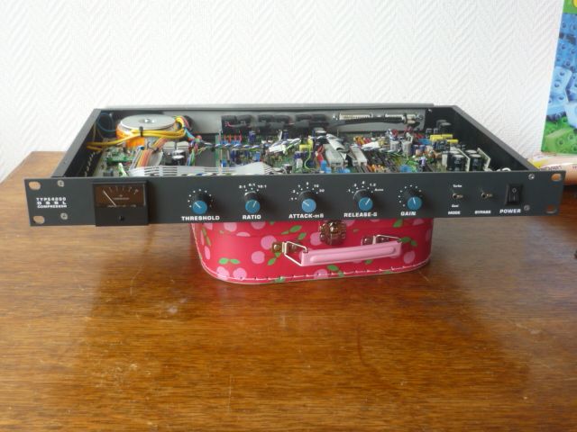
Pictures of a finished Gyraf modified SL552 unit (without the summing resistor network though) :
and
The mods for turning a 552 into a summingbuscompressor are described in this updated first post : Scroll down for the "htdiy"
(how to do it yourself)
----------------------------------------------------------------
Hi there,
I've got quite a lot of emails recently with questions how to wire the SSL SL552 IMO module, so I've decided to start a new thread for this.
First, let's tell what a 552 IMO actually is !
IMO stands for Independant Main Output. Basically, it's this :
stereo summing amp > balanced inserts> masterVCA> balanced inserts> balanced output. There are a few more bells and whistles, but not interesting enough to take into consideration for building a summingbox.
Regarding the summingamp : it uses MAT02 as summingfront end and is completely identical to summingstage as the SL557 module which is the masterbus of the 5000 broadcast console.
(a sidenote: SL557F is a 5000 Filmconsole module, which doesn't handle audio).
Here's the block diagram. Ignore the external input, TB input, and everything below that. It's of no use (although the external input can be of use).

Here's the pinout diagram. The last stage is used solely for adding the talkback and tone inputs to the signal, so, you can discard that for the standalone racking : Simply use the post vca sends as outputs.
In case you want to use the last stage : The postvca insert can be jumpered on the DIN41612 using common jumperblocks as used in computers. a drop of soldering will do the trick as well.
The connectors you need for this are 2x DIN41612 sockets (not plugs!), 96 pin ABC, or 64pin A+C.

This is a way to make a passive summing resistor network that will work with these modules. Note that it's be best to use low tolerance metalfilm resistors, or handmatch them in sets of four. SSL usually uses 0.1% tolerance for the audiocircuits (although they don't use passive summingnetworks in their designs). Connect all the ground/sleeves of the inputs to the ground of the SSL module.
One thing that has to be noted : This summingnetwork is something I found in the SSL docs, as an alternative for the standard active summing that’s used in the 5K console. However, together with the summingstage of the 552 this gives a boost of 6 dB. Kante and I have experimented with shunt resistors, but it’s not possible to get it right with only a shunt. (Increasing the 10K resistors to, say, 20K, should be an option though).

In case you have a few unbalanced lines that you want to add to the summingnetwork, it'd be best to wire the ground/sleeve of the output to the negative rail, and the plus to the positive rail (both via a 10k resistor of course). Don't connect the ground of the output to the ground of the summingnetwork.
Another good option, is to use the NYD design passive summing network. It’s somewhere here on the groupdiy site, so, hit the search button !
Udo is currently building a NYD summingnetwork, check this : SSL 552 Summing Box
PSU :
Regarding the PSU for SSL5k modules : I recommend the JLM audio 5 rail powerstation kits. a dual 18vac torroid in front will give you the desired voltages via the standard regulators.
If you're building a PSU solely for the 552, you could also use the 3 rail psu, and reverse the doubler rail into a negative doubler rail : You should reverse the caps and the diodes in the doubler circuit (including the chargepumpcaps), and use a 337 instead of a 317. This way a dual 15VAC torroid will do the trick. Note that the pinout of a 337 is different than the 317, so you should wire this one offboard.
EDIT : post from mrclunk and SSLTech :
I have tested this also, and it does work, as long as you don’t use more than 2 or 3 modules. So, for only the 552, this is a cost effective, simple solution.mrclunk said:Also the -24v rail is just for logic so doesn't need to be regulated.
So u could just tap off the -24v (ish) after the bridge and filter caps of your psu if using a 18-0-18vac transformer.
Oh, and before I forget !
Keep in mind that the amp produces heat, so, make sure that there's enough space inside the box.
so here it is. I hope you all like this project, and goodluck building yours !
---------------------------------------------------------------------------------------------------------------------------------
here are a few pics again of the 12 stereo input unit that I built a few years ago. Not that supergood looking, I know, but the wiring is done decently, and its sound is simply great. The summingresistor network is soldered directly on the sub-d inputs.
(btw, I haven't got this unit anymore, simply because I have built a bigger one, with 3 subgroups and active summing. )


……………………………………………………………………………………………………………………………………………………
Edit 24-11-11 :
Here's my recently finished SSL Summing Station Lunchbox :
http://www.groupdiy.com/index.php?topic=43999.msg585977#msg585977
Edit 1 Februari 2012 :
Here’s the necessary info for turning the 552 into a serious GSSL
Simply, by adding the GSSL sidechain stuff to the IMO’s VCA’s. This is even more simple than building a GSSL.
With this setup, you have an all complete SSL audiopath, with original SSL balancing and debalancing chips, paired temperature compensated DBX/THAT VCA’s for each channel, and of course the SSL summing stage as a luxurious bonus. (which you don't necessarily have to use : You can enter the VCA stage at the pre-vca insert return, thus bypassing the summing circuitry, so you can use it as standalone compressor also !)
What to do, is tapping off the audio signal in front of the VCA’s of the 552, route that to the sidechain circuit of a GSSL, take out the CV from the GSSL, and wire that to the 552 again. Wickedly simple !
Here the schematic and layout with the notes.
The 552 (just one channel shown by the way).

The modifications :
On both boards (85052 and 85152) :
-Remove the 2 resistors marked red . (R40 and R62) (edit : R40 doesn't need to be removed)
-Tap off the audio signal at point 3. (use the pad of the just removed resistor R62 that’s connected to RV5). This goes to the 47K resistors of the GSSL board (shown below in the GSSL board layout).
- Lift leg 3 of IC5, so it’s disconnected from 0v. The CV comes in at this point, so, solder a wire to it, and connect this to point 4 shown below in the GSSL boardlayout.
The GSSL board :
Only the components needed are shown here. Plus the gain make up pot of course !
A few notes :
-the 0v connection is not shown, but of course, it’s needed also. I don’t need to tell where to connect this, right ?
-Jumper the 2 resistors marked “2”.
-Replace the 2 resistors marked “1” with 4K7 resistors.
3 is where the audio left and right come in from the 552 boards,
4 is where the CV comes from, that go to the IC5 opamps on both 552 boards.

I guess that covers it……..
Of course, you can add the Turbo board from Expat to it, which is recommended , and also the SSC boards can be used with it. The wiring procedure for adding these boards, are the same as it would be for the normal GSSL.
Here a few pictures of the experiment. More to come !:


----------------------------------------------------------------------------------------------------------------------------------------------------------
Addition april 15th 2013 :
I've got some additional info : It's possible to power the 552 from the GSSL board.
The post VCA send will be the output of the module.
The following things will be removed :
the external input, and the post VCA circuitry including tone and TB insert, and mono output.
There are just a few simple things that need to be done to the 552 boards , then it's possible to take out the logic part, so you won't be needing the -25v line anymore.
That means, that you can use the GSSL +/-15 volt PSU part for powering the 552 module, by changing the 7815 and 7915 to 7818 and 7918 (and use a transformer with a dual 18v secondary.)
Here's how to do it :
The mods must be made on both boards.
Summing stage :
-remove TR1, TR3, TR7, and TR9.
-remove TR2 and TR4, jumper source to drain. (pins 2 and 1).
That’s easy, huh ?
Stuff that’s not in use, best is to take them out to reduce powerconsumption. Except for a few hybrid chips, all are socketed:
T85052 board :
Hybrid chips : H6, H7, H8 , H9, H10, H11, H12
Demux chips : IC 7, 8,9,10,11,12,13, 14, 17,
Plus on the T85152 board :
Audio chips : IC 7,8,9, 15, 16
Hybrid chips : H6, H7, H8, H9, H10, H11, H12 (H7 and H10 are soldered, you don't necessarily have to take them out).
Logic chips : IC 10, 11, 12, 13, 14.
The audiobalancing chips are valuable, so, keep them as spare. (85501 and 85502). The other hybrids are practically worthless.
------------------------------------------------------------------------------------------------------------------------------------------------------
Addition June 26th 2013 :
Pictures of a finished Gyraf modified SL552 unit (without the summing resistor network though) :

and

Last edited by a moderator:


![Soldering Iron Kit, 120W LED Digital Advanced Solder Iron Soldering Gun kit, 110V Welding Tools, Smart Temperature Control [356℉-932℉], Extra 5pcs Tips, Auto Sleep, Temp Calibration, Orange](https://m.media-amazon.com/images/I/51sFKu9SdeL._SL500_.jpg)


