SSL 552 Summing Box

GroupDIY Audio Forum

Help Support GroupDIY Audio Forum:

This site may earn a commission from merchant affiliate links, including eBay, Amazon, and others.
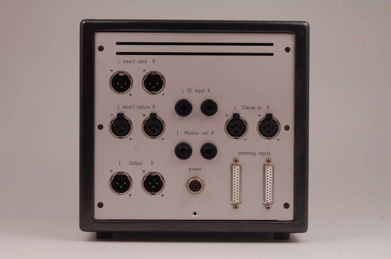
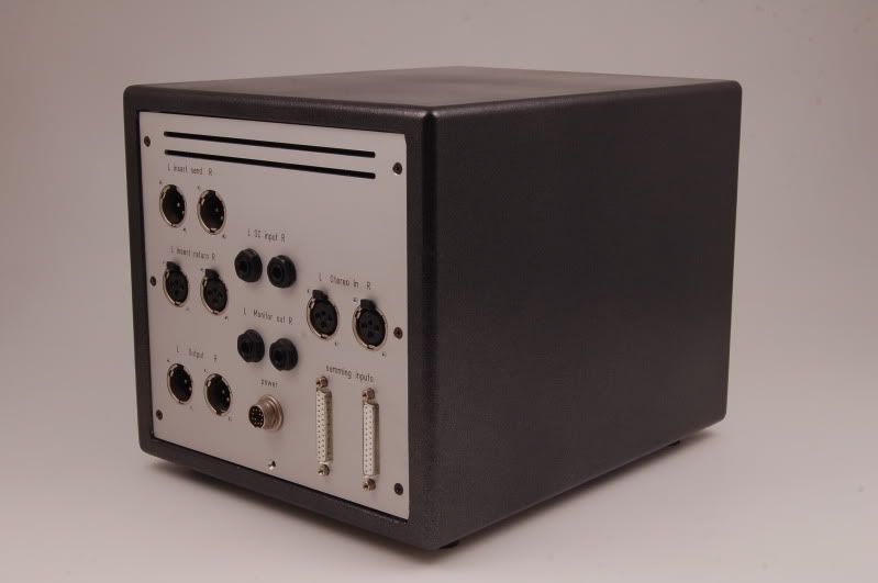
OK mine is done! and it works!!!! ;D
24 inputs via 3x 25 way Dsubs stereo out and a pre fader insert.

mixbus.jpg
 
Hi Neil,

nice to hear you´re back!
So you did it-great!
Now it´s time for some inside pics,no?
What type of module have you used and what about the psu-SL552 and JLM (just a guess)?
Did you use starground or AES for the i/o?

Best,

Udo.
 
Thanks!
Yes it took me a while but i got there in the end thank you and helterbelter for your help and encouragement!
I will take some inside pics for you next week and upload them.
The PSU im using currently is a JLM Powerstation in an external box because i have a big external PSU in the making that will power my whole SSL 5K mixer, il get some pics up of that too,
I actually used common earthing Krone blocks for the io like these:

http://www.canford.co.uk/Products/46-104_KRONE-237DB-Module

As they are very easy and tidy to wire and it worked out rather well, they are basically punch down bus bars used in broadcast and telecoms (if you are not familiar with them already).

Im now moving on to the rest of my 5K mini mixer build, there is light at the end of the tunnel!
 
Pretty cool!

Didn´t know the Krone blocks-nice idea.
However-are the i/o grounds attached to the chassis (AES) then or do they go together with the 0v of the IMO to the 0v (starground-point) on the external psu?
And another question:Did you use the resistor network as suggested by helterbelter (just 10Ks,no shunt)?
Looking forward to see the pics!

Go Neil go!

Best,

Udo ;)
 
;)
Im pretty sure i put the shields of the  25way D's all together and straight through to the shields of the XLR outs/Insert points so the audio shields are all common but isolated from the chassis.
Ive got a pretyy bad memory so il have to check for sure when i take some pictures.
Im pretty sure i kept all the audio isolated from the chassis.
I did use Helterbelters resistor network idea, just 9K1 (1% tolerance) resistors i couldnt get hold of 10K's at the time and it wont make a difference.
The unit is at my work place right now and i wont be back there until sunday so il get some pictures then.
 
DigitalMetal said:
;)
Im pretty sure i put the shields of the  25way D's all together and straight through to the shields of the XLR outs/Insert points so the audio shields are all common but isolated from the chassis.
Ive got a pretyy bad memory so il have to check for sure when i take some pictures.
Im pretty sure i kept all the audio isolated from the chassis.
I did use Helterbelters resistor network idea, just 9K1 (1% tolerance) resistors i couldnt get hold of 10K's at the time and it wont make a difference.
The unit is at my work place right now and i wont be back there until sunday so il get some pictures then.
THX for the info Neil,

best,

Udo.
 
Hi Neil,

Yes, I'm very curious for the innards !

Regarding adding the GSSL sidechain circuitry to the 552 VCA's :

This week I have ordered a couple of Turbo boards. I'm going to turn a 4 channel SSL SL595 line amp (that uses VCA's as outputfader), into a GSSL compressor. Not sure when I'll be finishing it, but if it turns out well, the same modifications can be done to the 552.

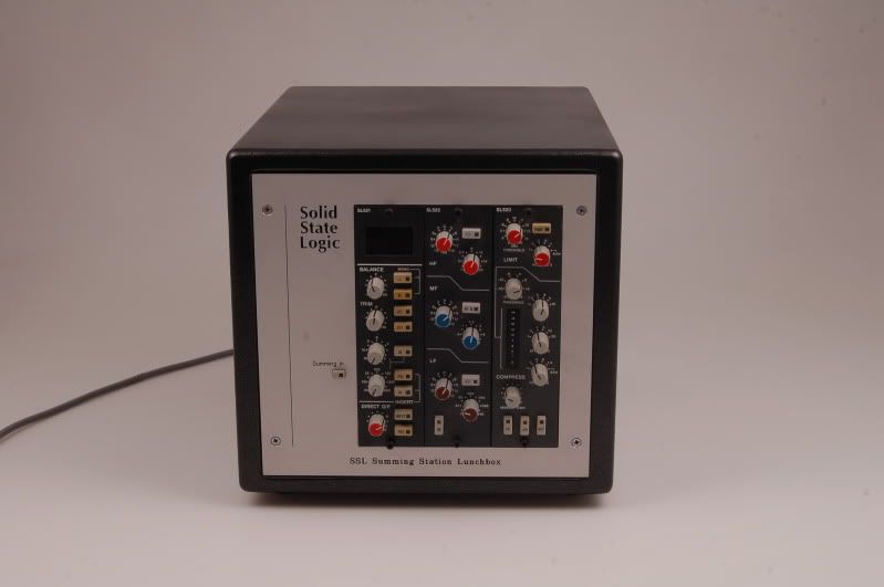
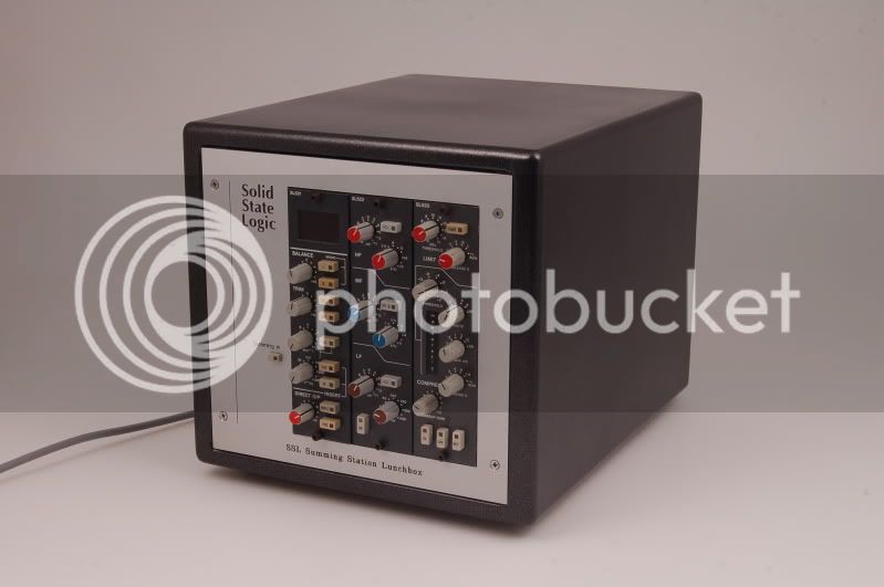
And here's my newly built SSL Summing Station Lunchbox.
It uses a 555F summingcard (the same summingcircuit as the 552), into a 521 stereoline amp, with a 522 EQ in the dyn/eq bus, and a 520 busscompressor in the insert.

It has 2x SubD inputs for the summing, and a stereo input via XLR. With the frontpanelswitch labeled "Summing In", the XLRs will be summed with the SubD's, when it's out, the summingcard is bypassed, and the stereo inputs will be sent straight into the 521.

I have modified the 521 a little bit. The insertswitchinglogic is disconnected from the audioswitching. The audioswitching of the insert is set to "on" permanently, so that the 520 compressor is routed in the insert all the time. The actual insert switch and the latchingcircuit is rewired to a pair of relays mounted on the rearpanel, that switches an external stereo insert in and out (xlr's on the rear, pre-compression).

I also have added a "Keith's balancing circuit" board for balancing the monitor outputs.

(for info about the 521 and the 522, check this thread : http://www.groupdiy.com/index.php?topic=41573.msg585969#msg585969 )

Front.jpg

Frontangled.jpg

Rear.jpg

Rearangled.jpg
 
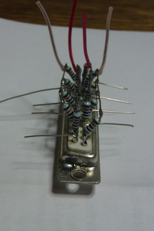
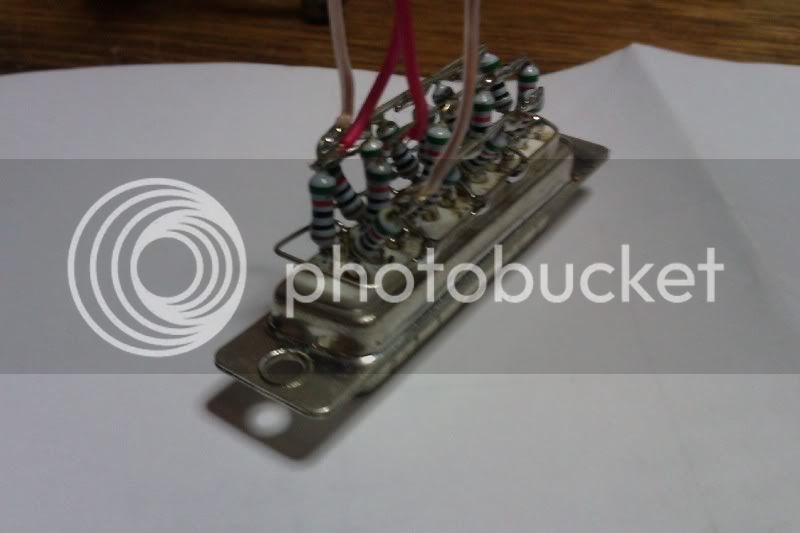
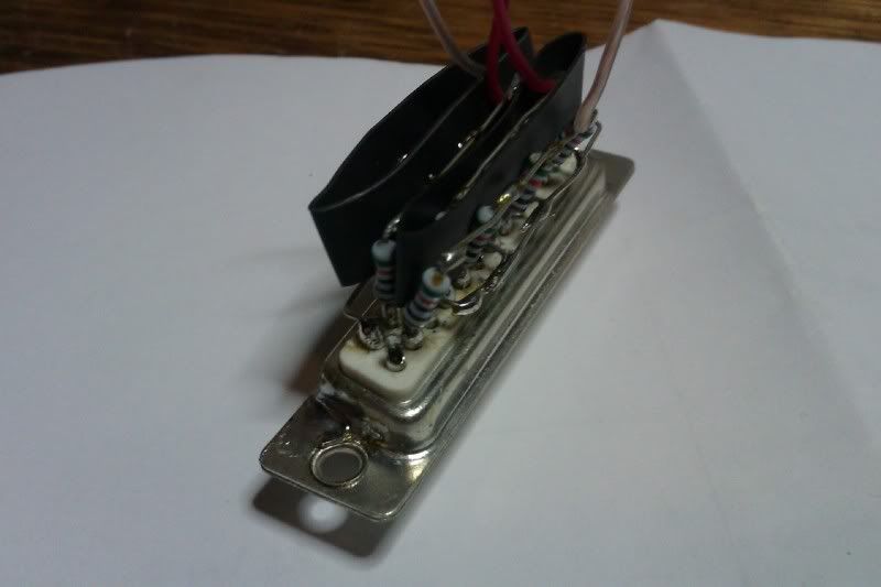
And here's how I've made the resistornetworks on the sub-d's. I hope my explanation (in crappy english) and pictures say enough, whahaha :

-Solder the resistors into the audio busses, and also solder wire into the grnd busses.
-Bend the groundwires to the side.
-make 4 rows : 1 row of negative odd, 1 row of positive odd, 1 row of positive even, and a row of negative even. Solder bridges to connect these :
IMAG0291-1.jpg


-Solder a ring around the subD to connect all the grounds. (not a closed ring, more like a U).
IMAG0293-2.jpg


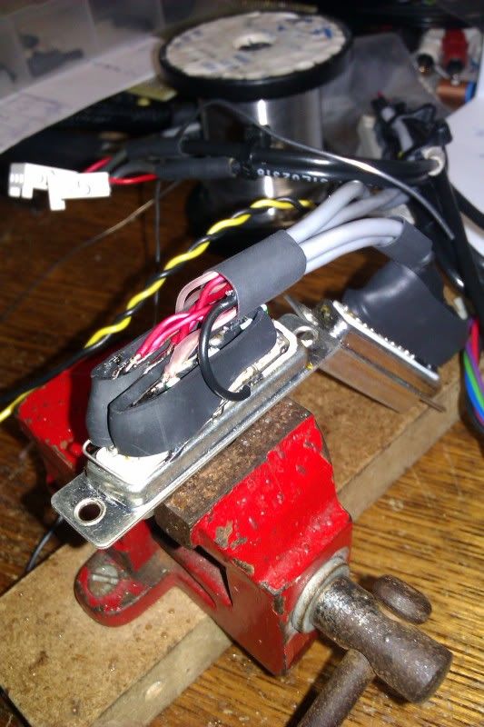
Isolate the 1st and 3rd row with heatshrink tube. The other 2 rows are then automatically isolated as well. (though, make sure the groundwires don't come near the audioconnections).
IMAG0294-1.jpg


Attach the wiring that goes into the summing amp.
IMAG0296-1.jpg


I don't have a picture made of the last stage !!!  But, in the last picture you can see a second sub-d connector that's finished. I use isolationtape to cover the top. And after that, I used a larger piece of heatshrink to keep everything in place, and to make sure the sticky tape residue won't come off, or out, after a few years.

Well.... I hope this makes sense to you all. If not, then ask, haha.

Greetings,

Paul
 
WOW Paul-AWESOME!!! :eek:

And nice to have you back of course ;D
I still have too much work in real life,but have started to do some of the passive "front stuff" following New York Daves´ schemo.
Still haven´t decided which way to go-either hooking these up to an IMO (leaving out the shunt resistors of course) or using 9K or SL501s as preamps.
Attached some pics of the Lorlins for L-C-R switching (MBB-type)-in the close-up you see where I "hide" the 10Ks for summing (0,1% resistors-yes Sir,I had  about a hundret left here,so why not use them ;D).Forced myself building 16 as minimum because I´ve got 2 Fireface800s now!
Meanwhile have also wired the mute switches;next step will be the level-pots as I have found the dual 5K log type finally(Bourns,small pots and affordable).Will take pics of them soon.

Cheerio my friends,

Udo.
 

Attachments

  • NYD-LCRs.jpg
    NYD-LCRs.jpg
    363.7 KB
Hi Udo, Hi Neil,

Thanks for the kind words : )


Regarding the shunt resistor in NYD's summing design : Maybe it's needed when you use a micpre as gainmakeup amp, but I'm pretty certain it's not needed with the 552.

Regarding the lorlins : Yes, wiring them will be some work, but I'm sure the result will be great : )
With your earlier diy works (that I have seen) in mind, I'm sure this will be superdecent and tidy.

 
helterbelter said:
Regarding the shunt resistor in NYD's summing design : Maybe it's needed when you use a micpre as gainmakeup amp, but I'm pretty certain it's not needed with the 552.
Yes,it´s needed ;)(arround 40 dB loss,impedance will be arround 200 Oms).
helterbelter said:
Regarding the lorlins : Yes, wiring them will be some work, but I'm sure the result will be great : )
With your earlier diy works (that I have seen) in mind, I'm sure this will be superdecent and tidy.
Let´s wait and see,hahahaha......
Took pics with the prewired mute switches some minutes ago (3p2T,the third is for switching leds for indication then).
Have fun guys,here´s the sweet little sixteen (in a box-what did you think ;D):


Attachments

  • 16 LCR+Mute.jpg
    16 LCR+Mute.jpg
    402.2 KB
I Found these pictures i completely forgot i took while building the unit, sorry for the bad quality i took them with my phone camera

sslmixbus1.jpg

Inside the finished unit


Very cool Neil!

I like the way using these Krone-blocks;will perhaps give them a try.Didn´t even know they´re existing before-great!
So it´s just about "clipping" or plugging the wires in or is there any special tool needed?
If so it would be very useful for me since I´m using massive(!) wires in  my build.
The level-pot is the original one as far as i can remember,correct?

Thanks a lot for the pics,beedtime now,it´s close to midnight here,

CU,

Udo ;)
 

Latest posts

Back
Top