


Regarding the following push-pull audio power amplifier LTSpice model:
This circuit was universal in old Germanium transistor radios and such. I am exploring different audio compression ideas and I need a single supply push-pull amplifier that has a high ratio of current drawn based on signal level. Meaning if the input signal level is high, the current drawn by the output is say 100 mA whereas if the signal is at or near zero, the current drawn is largely dependent on the bias of Q2 and Q3 which is probably a few mA. The model claims it can put 170 mA into the "speaker" and draw about 11 mA quiescent current but on a bread board the circuit does not yield a very good ratio. And I had to sprinkle the circuit with small caps to stop if from oscillating.
So I would like to understand the oscillation better so that I can increase the power / quiescent current ratio while maintaining some fidelity. If I could really get 100mA out of it and have a quiescent current of < 1mA that would be outstanding.
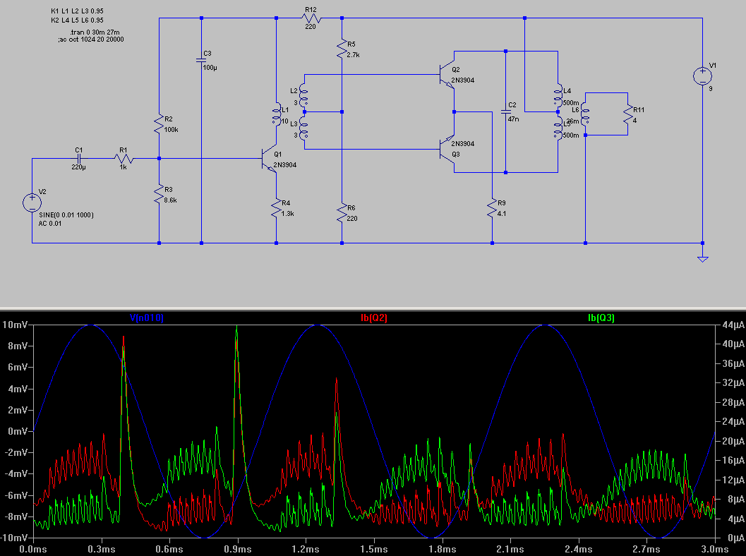
The model is stable if the bias control resistor R5 is 2.6K. But at 2.7K, as Q2 and Q3 start to turn off more, the circuit model oscillates as illustrated in the graphic. With the bias resistor at 2.6K, R9 has over 5mA through it.
Can someone speculate as to the source of the oscillation? How might I dampen it? I would rather not just blindly litter the circuit with capacitors. Can someone describe the mechanism of the oscillation so that I might focus better on how to eliminate the oscillation?
The model clearly shows the oscillation transcends the entire circuit. Meaning when oscillation occurs, the base of Q1 has noise, the bases of Q2 and Q3 are clearly oscillating as shown in the graphic, and the voltage across the 4 ohm "speaker" is severely distorted. So the flux in both transformers is going back and forth. But I am not an engineer so I don't really understand how to perform a proper circuit analysis.
This circuit was universal in old Germanium transistor radios and such. I am exploring different audio compression ideas and I need a single supply push-pull amplifier that has a high ratio of current drawn based on signal level. Meaning if the input signal level is high, the current drawn by the output is say 100 mA whereas if the signal is at or near zero, the current drawn is largely dependent on the bias of Q2 and Q3 which is probably a few mA. The model claims it can put 170 mA into the "speaker" and draw about 11 mA quiescent current but on a bread board the circuit does not yield a very good ratio. And I had to sprinkle the circuit with small caps to stop if from oscillating.
So I would like to understand the oscillation better so that I can increase the power / quiescent current ratio while maintaining some fidelity. If I could really get 100mA out of it and have a quiescent current of < 1mA that would be outstanding.
The model is stable if the bias control resistor R5 is 2.6K. But at 2.7K, as Q2 and Q3 start to turn off more, the circuit model oscillates as illustrated in the graphic. With the bias resistor at 2.6K, R9 has over 5mA through it.
Can someone speculate as to the source of the oscillation? How might I dampen it? I would rather not just blindly litter the circuit with capacitors. Can someone describe the mechanism of the oscillation so that I might focus better on how to eliminate the oscillation?
The model clearly shows the oscillation transcends the entire circuit. Meaning when oscillation occurs, the base of Q1 has noise, the bases of Q2 and Q3 are clearly oscillating as shown in the graphic, and the voltage across the 4 ohm "speaker" is severely distorted. So the flux in both transformers is going back and forth. But I am not an engineer so I don't really understand how to perform a proper circuit analysis.