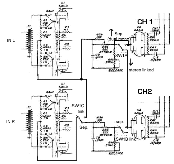
stereo link in vintage vari-mu units

GroupDIY Audio Forum

Help Support GroupDIY Audio Forum:

This site may earn a commission from merchant affiliate links, including eBay, Amazon, and others.

Val_r

Well-known member
Joined
Jun 5, 2004
Messages
306
Location
Naples, Italy.
Is there a way to create a stereo link button which can link two channels of vintage vari-mu limiters, such as UA175?

Has anyone tried out this?
 
You can simply connect the sidechains after the rectifier diodes. But both vari-µ tubes must be selected for same gain reduction curve, otherwise the stereo balance is moving while compression.
 
The Fiat solution is to tie the 2 control voltages together. The Ferrari solution is to disconnect the bottom tube grid control input and connect it to the top one's control voltage.
Then take the input to the top control amp and give it a 50/50 mix of both limiter outputs.

You get one set of adjustments only, and image tracking is usually optimum.
 
Still, the vari-mu tubes has to be very carefully selected to give any form of decent tracking. The gridvoltage-versus-gain in remote-cutoff tubes are everything but tightly-matched. And the inherent "dent" in the gain curve seems to occur all over the place..

Try out different sets of tubes to find some that does the job well enough for your purpose..

Jakob E.
 
Amen, Gyraf!

Tube matching in stereo units is far more elusive. Because it's not only to balance the push-pull sides properly, but to have the same gain/voltage plot on both channels. odds decrease fast.

That takes some serious curve tracer time. and lots of small piles of tubes on your bench with different numbers.

When you get those 175's linked, push a 1k tone thru both with several different degrees of gain reduction dialed in and see if the balance is wacky.
 
I hope it does make sense.
Any comment or suggestion much appreciated.

http://i41.photobucket.com/albums/e291/val_r/vari-mu-stereo-link.gif

Respect,

Val.

:idea:
 
Stereo Collins 26U-2 uses diode isolation after the attack/release controls of each channel, then provides a SPST link switch connecting through a 47K resistor. There's also 0.01 mfd to ground at the link point in each channel. The diode isolation keeps the side chains separate, but both available.
 
Yes, but not scanned. Identical to the 26U-1 except for stereo link and faster minimum release resistor. And two channels. I've modified mine extensively.
 
Does it operate the attack and release controls independently for each channel?
How is the stereo tracking?

It would be fine if you had the time for scanning the schema and post in turn.

Respect,
Val
 
yes independent control with linking. Stereo tracking is fine for my crude rock and roll purposes. You have to set it up with tones since you have input and output attenuators, along with two sets of attack and release, and in my case stepped ratio's too. I've mixed several records through it. Some have been acoustic folk records with lots of stereo miking, which seems like a fair enough test. Set up with tones means rough in the limiting you want, then put tones in and check setting alignments, then go back to mixing.

scan when i can. for now, find the 26U, multiply times 2, add the six parts I mentioned, you have it. The other parts I didn't mention; also 10M bleeders around the isolation diode back to the top of C11, and the PSU has no chokes.

here it is:

http://www.collinsradio.org/archives/manuals/26U-1-_07-58_.PDF
 
[quote author="emrr"]yes independent control with linking. Stereo tracking is fine for my crude rock and roll purposes. You have to set it up with tones since you have input and output attenuators, along with two sets of attack and release, and in my case stepped ratio's too. I've mixed several records through it. Some have been acoustic folk records with lots of stereo miking, which seems like a fair enough test. Set up with tones means rough in the limiting you want, then put tones in and check setting alignments, then go back to mixing. [/quote]

Oh thanks. That is the technique I'm adopting too! :thumb:

This way is easier and you operate attack and release pots from ch1 for both channels.

vari-mu-stereo-link.gif


I cannot figure out where those isolation diodes are located.

[quote author="emrr"]scan when i can. [/quote]

Please do that.

Comments welcome.

Respect,

Val
 
at the point where the side chains join one another, to pass DC bias and prevent interaction between side chain circuits.
 
The Fiat solution is to tie the 2 control voltages together. The Ferrari solution is to disconnect the bottom tube grid control input and connect it to the top one's control voltage.
Then take the input to the top control amp and give it a 50/50 mix of both limiter outputs.

You get one set of adjustments only, and image tracking is usually optimum.
Not sure if I'm asking the right question but, if you send an ac signal from a channel to feed another channel's control amp, wouldn't that actually be injecting that sending channel's ac signal into the other channel's output before the control amp as well?
 
Both ties are post-rectifier, effectively taking out one channel's Thr, Rat, Art, Rel.
 
Both ties are post-rectifier, effectively taking out one channel's Thr, Rat, Art, Rel.
Thanks. I get that from the fiat solution but I'm reading the second solution as input/pre rectifier? No?
Then take the input to the top control amp and give it a 50/50 mix of both limiter outputs.
 
Last edited:
Hm, not sure what 'fiat' means, but I read it to mean two sets of control (left and right) just tied together -- either at one point or at two.

AC tied together before the rectifier makes whatever sidechain(s) deaf to stereo (which can be interesting too).
 
Hm, not sure what 'fiat' means,
He's saying the cheaper car "fiat" version is one way but the more expensive car "ferrari" method is the second way.....

"The Fiat solution is to tie the 2 control voltages together. The Ferrari solution is to disconnect the bottom tube grid control input and connect it to the top one's control voltage.
Then take the input to the top control amp and give it a 50/50 mix of both limiter outputs.
You get one set of adjustments only, and image tracking is usually optimum."

Maybe you're right and the control amp isn't meaning rectifier..

So like this?50/50 mix of limiter outputs means threshold the same?
 

Attachments

  • AM-864_Schem slave question 1.jpg
    AM-864_Schem slave question 1.jpg
    481.1 KB
Last edited:
One interesting way I found is to tie together at the control amp (vca or tube) but NOT after the rectifier before Thr/rat/att/rel. That way the control voltages stay independent for left and right (e.g. panned instruments), but then mix 50:50 at the control amps.

Also tie after the rectifier and it's two sidechains in parallel mangling the same signal, e.g. one channel catches peaks, the other channel acts as a leveller. Of course the result is a mix. -- I guess this is the fiat ?
 

Latest posts

Back
Top