


Its possible to use a 961/962 Studer meterbridge on 169/269 consoles.
I post this howto since I've not found any documentation about it.
The only, insignificant, missed features are [studio on, ready, call] LEDs.
All the rest works perfectly, meters, correlator, FAST LED and PFL speaker.
I've done that on a stereo 269 and a 962 stereo meterbridge,
with PPM meters and correlator, but I'm sure the same procedure
will be ok for other cases.
My 269 monitor unit is 4ch Type 3 [pag 229 of Studer manual].
We have 3 issues to solve:
A] incompatibility of DB25 pinout in 169/269 vs 961/962:
DB25-1:
PP3-9 (violet) -> chassis on 169/269, -6V bulb illumination on 961/962
DB25-6:
PP3-10 (white) -> -8V for the grms on 169/269, -6V LEDs power source on 961/962.
DB25-23:
red/white cable from R75 (0V) on 169/269, call LED sign in 961/962
[note that we already have the 0V on DB25-8]
DB25-24: not connected on 169/269, studio LED sign in 961/962
DB25-25: not connected on 169/269, ready LED sign on 961/962
N.B. on my meterbridge board, the connection of the resistors/LEDs are different than the ones
on the 961/962 service manual [pgg 181 and 182], also if my 962 bridge's onboard printed number [1.961.902.81] is the same as the one in the manual.
on manual:
DB-23 -> R905
DB-24 -> R906
DB-25 -> R907
on my board:
DB-23 -> R906
DB-24 -> R907
DB-25 -> R905
So, double check yours!
B] giving the correct voltage to the grms:
they want -8V as ground, having 0..-8V [instead of 961/962's 0..4.2V] as limiting value from 169/269 master unit module's limiter.
they need also to have the red/blue cables swapped, because of the different polarity
of the signals in 169/269 vs 961/962.
We'll use DB25-23 to carry the -8V from the 169/269 monitor module micro-PSU, accessible on PP3-10.
And, of course, we'll add 10.65k resistors to R908, R910 [and R912 and R914 for 4ch version].
I've used 11.73k instead, but its not an issue, there are R909 R911 etc trimmers.
C] giving -6V for the LEDs [ok, its only the "FAST" LED, but it is useful]
and the meters bulbs [I dont have them, and also dont know if it could be a problem for the PSU..
anyway, better to have the option]:
A regulator + cap fixed on 961/962 board, with -15V onboard as input, does the job.
N.B. dont forget to add an heatsink to the regulator if you plan to use many bulbs.
Now, to the how-to:
Grab the 169/269 monitor module, and:
1] unplug the cables in PP3-9 (violet) and PP3-10 (white), and insulate them
[they go to the DB-25 connector].
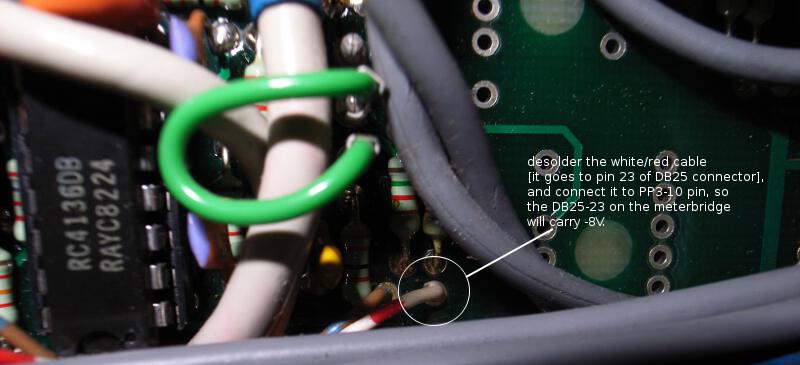
2] desolder the red/white wire going from R75 to DB25-23 (0V on 169/269, call LED sign on 961/962),
and connect it to PP3-10 [dont worry, there is 0V on DB25-8 too].
we'll use it to give -8V ground to the gain reduction meters on the meterbridge.
Monitor module img 1:
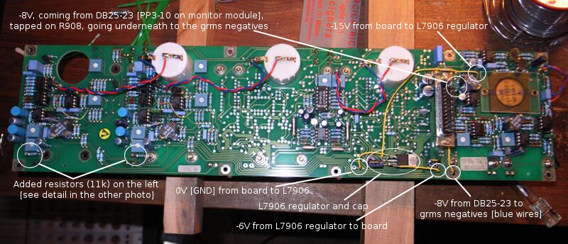
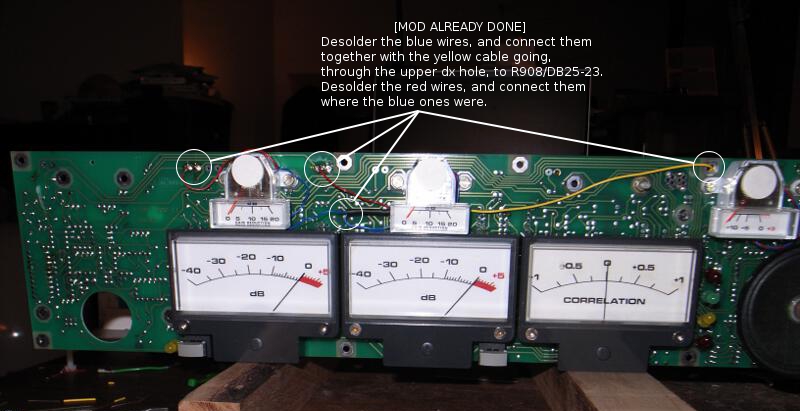
Next instructions on 961/962 meterbridge's mods are on these pics:
Meterbridge img 1:
N.B. typo in image, the resistor is R906, not R908
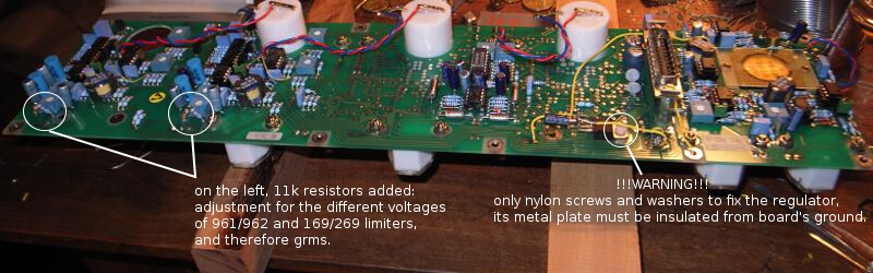
Meterbridge img 2:
Meterbridge img 3:
N.B. You can also cut&lift the other 2 resistors before LEDs on meterbridge board, just to be sure
DB25-24 and DB25-25 will not create any problems, also with 169/269 monitor units different than mine.
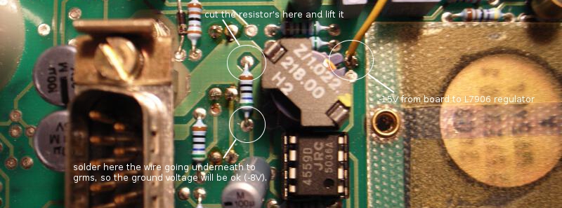
Meterbridge img 4:
N.B. typo in image, the resistor is R906, not R908
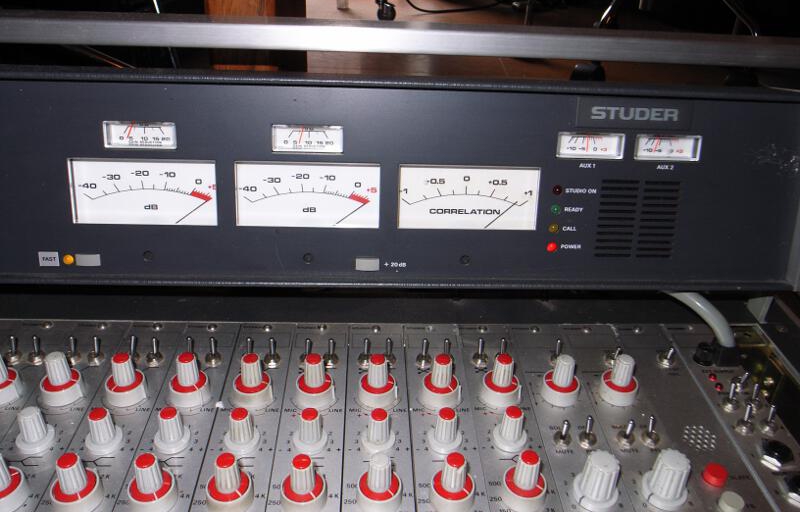
Finally, here is the meterbridge connected to the 269, in all its glory:
I post this howto since I've not found any documentation about it.
The only, insignificant, missed features are [studio on, ready, call] LEDs.
All the rest works perfectly, meters, correlator, FAST LED and PFL speaker.
I've done that on a stereo 269 and a 962 stereo meterbridge,
with PPM meters and correlator, but I'm sure the same procedure
will be ok for other cases.
My 269 monitor unit is 4ch Type 3 [pag 229 of Studer manual].
We have 3 issues to solve:
A] incompatibility of DB25 pinout in 169/269 vs 961/962:
DB25-1:
PP3-9 (violet) -> chassis on 169/269, -6V bulb illumination on 961/962
DB25-6:
PP3-10 (white) -> -8V for the grms on 169/269, -6V LEDs power source on 961/962.
DB25-23:
red/white cable from R75 (0V) on 169/269, call LED sign in 961/962
[note that we already have the 0V on DB25-8]
DB25-24: not connected on 169/269, studio LED sign in 961/962
DB25-25: not connected on 169/269, ready LED sign on 961/962
N.B. on my meterbridge board, the connection of the resistors/LEDs are different than the ones
on the 961/962 service manual [pgg 181 and 182], also if my 962 bridge's onboard printed number [1.961.902.81] is the same as the one in the manual.
on manual:
DB-23 -> R905
DB-24 -> R906
DB-25 -> R907
on my board:
DB-23 -> R906
DB-24 -> R907
DB-25 -> R905
So, double check yours!
B] giving the correct voltage to the grms:
they want -8V as ground, having 0..-8V [instead of 961/962's 0..4.2V] as limiting value from 169/269 master unit module's limiter.
they need also to have the red/blue cables swapped, because of the different polarity
of the signals in 169/269 vs 961/962.
We'll use DB25-23 to carry the -8V from the 169/269 monitor module micro-PSU, accessible on PP3-10.
And, of course, we'll add 10.65k resistors to R908, R910 [and R912 and R914 for 4ch version].
I've used 11.73k instead, but its not an issue, there are R909 R911 etc trimmers.
C] giving -6V for the LEDs [ok, its only the "FAST" LED, but it is useful]
and the meters bulbs [I dont have them, and also dont know if it could be a problem for the PSU..
anyway, better to have the option]:
A regulator + cap fixed on 961/962 board, with -15V onboard as input, does the job.
N.B. dont forget to add an heatsink to the regulator if you plan to use many bulbs.
Now, to the how-to:
Grab the 169/269 monitor module, and:
1] unplug the cables in PP3-9 (violet) and PP3-10 (white), and insulate them
[they go to the DB-25 connector].
2] desolder the red/white wire going from R75 to DB25-23 (0V on 169/269, call LED sign on 961/962),
and connect it to PP3-10 [dont worry, there is 0V on DB25-8 too].
we'll use it to give -8V ground to the gain reduction meters on the meterbridge.
Monitor module img 1:
Next instructions on 961/962 meterbridge's mods are on these pics:
Meterbridge img 1:
N.B. typo in image, the resistor is R906, not R908
Meterbridge img 2:
Meterbridge img 3:
N.B. You can also cut&lift the other 2 resistors before LEDs on meterbridge board, just to be sure
DB25-24 and DB25-25 will not create any problems, also with 169/269 monitor units different than mine.
Meterbridge img 4:
N.B. typo in image, the resistor is R906, not R908
Finally, here is the meterbridge connected to the 269, in all its glory: