Studer 900 - Racking

GroupDIY Audio Forum

Help Support GroupDIY Audio Forum:

This site may earn a commission from merchant affiliate links, including eBay, Amazon, and others.

saint gillis

Well-known member
Joined
Nov 4, 2012
Messages
889
Location
Brussels - Belgium
Hi!
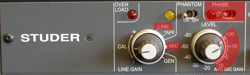
I'm putting in a rack 2 Studer 900 channel strips, the complete desk schematics are available here :
ftp://ftp.studer.ch/public/products/Mixing_Analog/900/Manuals/

Here the channel strip detailled schematic :
http://gypsyfarm.free.fr/echange/900_Op_Serv-199.jpg

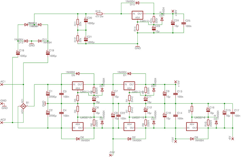
I ve made a PSU, 2x15V / -24V / -6V, it works quite fine but still few problems :

studer-900-forum.jpg


1) When I'm on the 4 lowest microphone gain positions, I got a hum, notice that for all the other positions it works perfectly!

2) Also notice that when I have selected the "LINE" input, I still have a hum when one of the 4 lowest microphone gain positions is selected (those positions have no effect on the line gain, it only plays on the mic gain, but the hum is still there)

3) When I'm using the "LINE" input and inverting the Microphone "Phase", a big uggly hum appears, when I'm on the "MIC" input position I can invert the phase without a problem...

---------

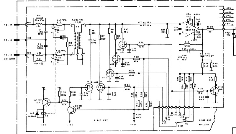
The -6V works with a rail called "0V L" "0V DIGITAL", here is the specific Mic Preamp schematic :
studer_preamp.jpg


Do you think the -6V rail should come from an specific PSU with its own isolated ground?
 
0V L "Logic"

I think part of your pb are after the shematic you show here, where the input selector act on all logical FET switch,
something always open in the mic input.

But as all your problems come when logical FET switching operate from 6v (input attenuation, input selector, phase flip), maybe there is something in this PSU rail
No pb with the FET switch on low/hi filter operating on the 24V rail ?

For info, in my Studer (other series) audio and logic/signalisation have different regulator

Zam
 
The -6v supply is the logic supply. In the lowest 4 positions the pad relay is operated. This will draw considerable current from the power supply. Is this current draw causing the power supply to run out of capability, or is there insufficient filtering in your supply?
Or have you commoned up the grounds in the wrong place?
 
zamproject said:
But as all your problems come when logical FET switching operate from 6v (input attenuation, input selector, phase flip), maybe there is something in this PSU rail
No pb with the FET switch on low/hi filter operating on the 24V rail ?
Yes I ve just checked it, some little hum when low/hi filters' led is on..
Still have to re-check all the ground connections
 
The way that supply is done you are pulling all the relay current through your - 15 volt supply. You need to build a completely separate -6v supply. So you need another transformer outputting about 12 volts d.c. and then straight to the -6v regulator.
 
radardoug said:
The way that supply is done you are pulling all the relay current through your - 15 volt supply. You need to build a completely separate -6v supply. So you need another transformer outputting about 12 volts d.c. and then straight to the -6v regulator.

yes and it's the same for the -24 !!!
try to find transformer with 3 output for +/-15, -24, -6
 
btw, if have a traco psu that was in an studer rack for +-15v, if you need that one, let me know.
 
saint gillis said:
Even with about 1,5Amp on each rail? I mean each channel has a quite small consumption and logic currents are small currents?
You have the unit running, you can meter each supply with a current meter and find out what the current draw is for each section, and build a supply accordingly.
 
radardoug said:
You have the unit running, you can meter each supply with a current meter and find out what the current draw is for each section, and build a supply accordingly.
So, with all the relays on, 10k loads on the outputs, 2 channel strips :
+15V -> 135mA
-15V -> 135mA
-6V -> 130mA
-24V -> 4mA

All the grounds are linked, excepted "0V INT" and "0V REFEFERENCE",
also I ve removed ICs 111, 112, 113, 114 and 115 (at the right end of the schematic)
 
As an experiment I have fed -6V & 0VL with a separated PSU, here are the strange behaviour I ve observed :
1) Whatever the position on the switch (Line / Mic / Tape / etc) I have at the output the sound from the line input AND from the Mic input.
2) I have a hum when the mic gain switch is on "-10" position
3) When I invert the phase switch I have no sound at the output, and the "filter in" leds light even if the filters are off.

- Then I have removed the ext -6V, and I ve observed exactly the same behaviours except the filters led that were always off -

So looks like the 0VL and 0V must be linked...

(Must say that ext -6V was in fact -6,7V)
 
If you look in the full drawing, the audio 0 volt and the logic 0 volt are linked.
If you float the logic 0 volt, strange things will happen. This module uses lots of fet switching, the control side of the fets is at high impedance, if you don't tie your grounds together leakage will cause all sorts of strange paths. Study the drawing more, and understand what is happening.
 
radardoug said:
If you look in the full drawing, the audio 0 volt and the logic 0 volt are linked.
If you float the logic 0 volt, strange things will happen. This module uses lots of fet switching, the control side of the fets is at high impedance, if you don't tie your grounds together leakage will cause all sorts of strange paths. Study the drawing more, and understand what is happening.
Alright, however the PSU is not undersized and I don't know where to start to find out what can be the cause of the hum when the phase is inverted and the mic pad activated...

Do you think it s a mistake to remove ICs 111, 112, 113, 114 and 115 and not to take care of "0V INT" and "0V REFEFERENCE" ?
 
radardoug said:
0v INT is created by IC113, so if you remove IC113 you need to ground 0v INT, or it will be floating.
Ok great I ll try that! so my problems may come from a kind of conflict between -24V at the far right side of the schematic ("BUS SELECTOR" fets) and the unconnected "0V INT" ?
 
I ve grounded "0V INT" , still got the same problems..
Then I also grounded "0V REFERENCE" and still the same..
Tomorrow I ll try to put in place the ICs I ve removed and to ground "0V REFERENCE"
  There are some things about thoose grounds pages 54-58 of the PDF but I m not understanding everything, I ll read it some more times to try to understand..
ftp://ftp.studer.ch/public/products/Mixing_Analog/900/Manuals/900_Op_Serv.pdf
 
I ve try to put all the missing ICs in place and to ground "0V REFERENCE" , same hum, then I ve also grounded "0V INT", same hum, then I ve grounded only "0V INT" it was worse
  There is also quite a lot of hum on the mic channel..
My lack of knowledge prevents me from seing the way for the solution...
 
I tried something I should have tried before :
I took an external -6V and linked the ground, it is far better for the hum when the mic pad is activated, still the pbm when the phase is inverted, now I have to try with an external -24V...
 
Back
Top