Hi, The Fet impedance Buffer will take a High impedance source Like that comeing from a Tube and covert the Impedance down to something in the Neighbourhood of between 50ohms to several hundred Ohms and can also be configured to boost the Gain comeing from the Tubes....
The thing about Fets is when the Clip they do so in a simular way as Tubes do which is why Fets and other transistors are now used in the Place of tubes (From what I have read).....
A Circuit like this should work ....
Which also has Provisions for Gain Boost but you might have trouble finding the 2N5571 like I did so maybe something simpler like this would be easier...
But this would probably have better Performance:
After the Fet buffer you can just use this simple circuit to create a Inverted (Ballanced) output...
But in a Battery powered situation you might want to replace the Opamp with a Lower power one like maybe the TL072 in which case you would replace the 10k input resistors to 22k (I"m sure there are better low power opamps than the TL072).....
I"m sure with the Schematics I posted in this thread you should have a Fairly good idea how to implement the Tubes and the Fet Buffer and the Ballanceing useing Mostly discrete components accept for the opamp as I had little more that this info to go on when I started with my tube pre design....
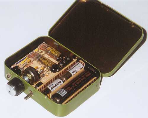
Here is a pic on my mostly stuffed prototype PCB..(Just have to wait for some High Value Resistors to show up in the Mail)
You can hardly see them as Tubes they are so small (and it is a ****** Pic)so you have to look closely but they are in the Top center and Right of the PCB close to the Yellow and white Polly Caps....
I think most of the designs that use these tubes use 2 or 3 tubes because these tubes do not put out very much signal so you might have to use a few to get the signal strong enough for output...
I use a Transistor based Front end to feed the Tubes a Strong signal and also built a Post Gain stage to boost the Gain from the Tubes even more....I have it set up so the First tube runs at Unity gain and the next one has adjustable gain , then I added the Fet impedance Buffer to lower the output impedance which then goes into a Clipping Indicator (Led) and then a 20db Pad and then it goes to a Dual Opamp for Ballanceing and then to output and useing ferrites on both the input and output for Interferance suppresion.....
I am feeding the Plate Voltage from a +48v Phantom feed regulated with a 10K resistor and a 20v Zenner (the plate runs from 15v to up to 30v with 22v being the recomended Voltage) and I run the 1.25v Fillament off of the +15v Rail useing a 1k resistor and a 1.5v Led as a Regulator......
I have no idea if the Circuit will even work but that I guess is part of the Fun of DIY.....
I"ve only been doing electronics for a few months so I don"t know too much so I get most of my Ideas from useing Parts of different designs and Throwing them together and I also just get Ideas that I have no idea how to implement so I just do what I think should work and Hope for the Best and sometimes it works great and sometimes I have to make a few changes to get it to work but more often than not the whole Thing goes up in smoke and Sparks but I don"t get discouraged for very long and I am usually blowing something up soon afterwords.....
But if there is something I can help you with just let me Know and I"ll try to do my best with the Limited knowlege I have.....
Cheers
PS: I also have quite a Huge Schematics collection so if there is something you need I might have it ...OOhhh I don"t have any Tube Hearing aid schematics...Sorry But I do have several Battery powered preamp schematics....
 [/quote] So, what is this thing and what SubMinis does it have in it? Is there a schematic available?